-
-
Notifications
You must be signed in to change notification settings - Fork 348
Radio hardware specifications for EdgeTX
(page under construction)
- MCU: presently only STM32F429BI and STM32F439BI with 2 MB flash are supported. Running at 168 MHz. Support for STM32F7/H7 MCUs is planned from EdgeTX v3 onwards.
- SDRAM with minimally 8MB
- SD/microSD card slot or embedded SD NAND (e.g. XTX XTSD04G, minimally 512 MByte). Connectivity via SDIO preferred.
- Color display with minimally 480x272 pixels. Presently supported resolutions 480x272, 480x320 and 320x480 pixels. With EdgeTX v3, 800x480 pixel support is planned.
- Either touch-screen or keys for navigation, or both. Presently supported touch-screen controllers: GT911, FT6236, CST836U If no touch-screen is available, minimally, Menu, Enter, Return/Exit, Up, Down, Page and two horizontal trim buttons should be availabe. Up/Down can be substituted with an encoder/roller.
- Display connectivity via RGB565, future support for MIPI-DSI is planned for EdgeTX v3.
- Present display controllers supported: internal STM32F4, ST7796S, HX8357D, ILI9481, ILI9486, ILI9488, NT35310.
- possibility to flash the firmware via USB-DFU (with or without dedicated DFU button)
- constantly enabled energy source for the real-time-clock
- possibility to power down the radio from main microcontroller
- possibility to sample the voltage of the main battery
- Neopixel RGB LEDs only on PWM capable pins with DMA support
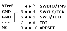
- Serial-Wire-Debug header. Either pads for 2x5 pin 0.05" header
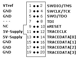
or full-ETM trace header with 2x10 pin 0.05" header:
- USB-C device mode connection
- For radios with an internal module, lines to put the module into flashing mode to perform pass-through flashing
- Display backlight control via PWM - connection to hw-PWM capable pin on the MCU
- Gimbals with either analog, PWM (e.g. TLE4998P3), SPI ADC (e.g. ADS7952) or UART communication
- Switches as digital or analog inputs
- haptic vibrator, via binary or PWM output
- support for additional key navigation input. Supported keys: Enter, Return, Page>, Page<, Up/Down, System, Model, Tele.
- support for encoder/roller user input
- Audio output via STM32 integrated DAC or via SPI codec (e.g. VS1053B is already supported)
- Explicit audio volume control, e.g. via I2C, SPI or further DAC output
- Explicit audio mute pin
- in case of integrated charging circuitry/circuitries, feedback to main MCU about charging status of each charger
- for external RF module bay support: either JR-micro or JR-nano bay
- If trainer socket present: in/out connected to hw-PWM capable pins
- SPI flash
- I2C EEPROM
- Bluetooth module via UART
- IMU (e.g. LSM6DS33)
- SpaceMouse module
- MCU: STM32F2 and STM32F4 with minimally 512 kByte flash (for new radios only STM32F4 with minimally 1 MB flash)
STM32F2 running at 120 MHz, STM32F4 running at 168 MHz - SD/microSD card slot or embedded SD NAND (e.g. XTX XTSD04G, minimally 512 MByte)
- Monochrome display with either 128x64 pixels or 212x64 pixels.
- possibility to flash the firmware via USB-DFU (with or without dedicated DFU button)
- constantly enabled energy source for the real-time-clock
- Keys to navigate the menus. Minimally, Menu, Enter, Return/Exit, Up, Down, Page and two horizontal trim buttons should be availabe. Up/Down can be substituted with an encoder/roller.
- possibility to power down the radio from main microcontroller
- possibility to sample the voltage of the main battery
- Neopixel RGB LEDs only on PWM capable pins with DMA support
- Serial-Wire-Debug header. Either pads for 2x5 pin 0.05" header
or full-ETM trace header with 2x10 pin 0.05" header:
- USB-C device mode connection (minimally for new radios)
- For radios with an internal module, lines to put the module into flashing mode to perform pass-through flashing
- Display backlight control via PWM - connection to hw-PWM capable pin on the MCU
- Gimbals with either analog, PWM (e.g. TLE4998P3), SPI ADC (e.g. ADS7952) or UART communication
- Switches as digital or analog inputs
- haptic vibrator, via binary or PWM output
- Audio output via STM32 integrated DAC
- Explicit audio volume control, e.g. via I2C, SPI or further DAC output
- Explicit audio mute pin
- in case of integrated charging circuitry/circuitries, feedback to main MCU about charging status of each charger
- for external RF module bay support: either JR-micro or JR-nano bay
- If trainer socket present: in/out connected to hw-PWM capable pins
- SPI flash
- I2C EEPROM
- Bluetooth module via UART
- IMU (e.g. LSM6DS33)
Getting started with Git
- Workflow for GitHub noobs
Building and debugging EdgeTX
- In a webbrowser with Gitpod
- Windows 10 (MSYS2)
- Docker with Windows 10
- Ubuntu in a WSL2 under Win10
- Ubuntu 20.04
- MacOS 10.15
- MacOS 14.1
Modifications:
- Flysky Hall Sticks Mod
- Flysky FRM303 Mod for TX16S
- Flysky PL18 & PL18EV Hardware Mod for Complete EdgeTX Support
- Flysky NB4+ Hardware Mod for Complete EdgeTX Support
- Flashing EdgeTX to Flysky PL18 or Paladin-EV
How to unbrick your radio with STM32CubeProgrammer
DMA mappings of radios:
- RadioMaster TX16S
- FlySky NV14
Interrupt usage of radios:
- RadioMaster TX16S
Implementation notes:
- YAML Parser/Generator
- Mixer synchronisation
Customisable switches:
- Customisable switches
Deprecated:
- Windows 10 (Visual C++)

