Gen2.1.12 (ex2.14) - PPM and PWM RC remote? #36
Comments
|
It seems to be different from photos on main page. So could be different layout. Controller looks like ok (gd32f130 c6t6?); battery 24V |
Hello @pacraf, Thank you for your very quick reply, I saw your 4-wheel vehicle and I want to do roughly the same thing, only I want to attach a flight controller and GPS to it so that it can work autonomously. |
|
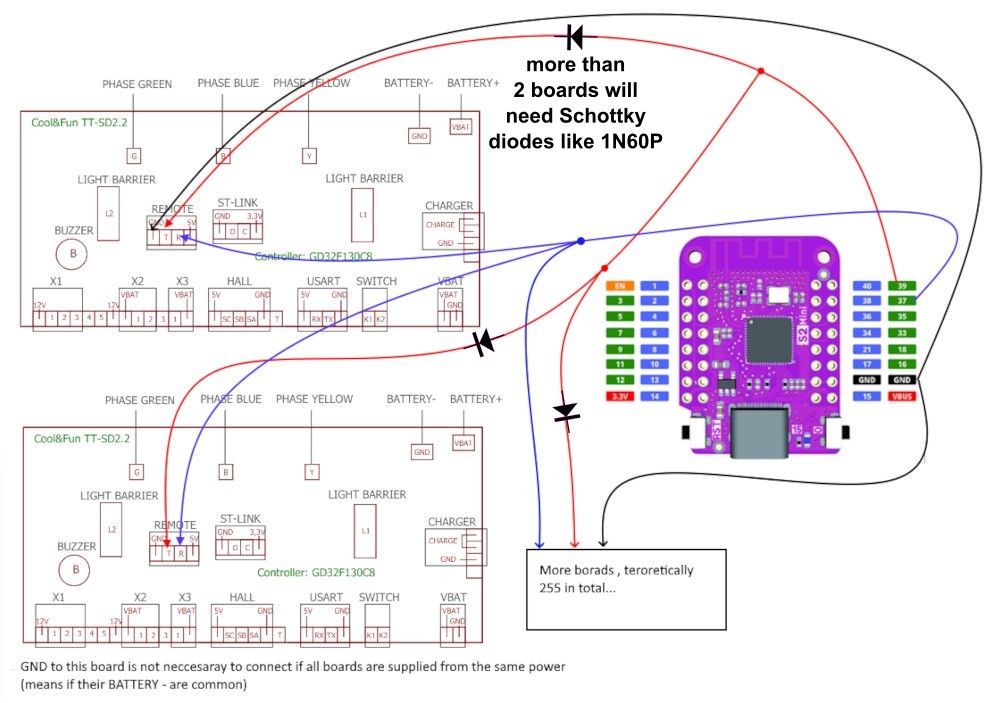
Wiring is shown here, as it is lolin s2 connected to 4 boards, with diodes , as you can see on main page of this repo. Additionally you will connect your receiver or FC. I also experimented with pixhawk, but finally I have it only with RC receiver. I am stuck now with hardware making, so proper box , installing motors , making it rain proof… |
Hello, Thank you for your answer. |
But if you want other control than PPM, then you need to transfer values from your RC to iSpeed and iSteer… this is generally idea. 2 yes and no. All boards are connected like on diagram. 4 in my case. In this scenario there is no master and slave (remove this cable) , but all boards are connected like this diagram shows. All are “singles” addressable one by one , with unique ID. This ID you have to compile with Keil so each bin file is different. Don’t load everywhere the same file because this will be mess. All will want to respond to lolin on the same time so this will not work. Take your time and read some threads on thin git. You will understand all aspects, there are other options to control 4 wheeler but I did not use them .
|
If the SLAVE board copies everything the MASTER board does, could I load the firmware for the SLAVE in the MASTER and vice versa? |


|
Hmm scenario like you proposed on diagram (but one thing different, that in fact master connecting with lolin , and then slave connected to master. You know what I mean? Just change on your diagram words master and slave). So this scenario is possible, however not tested by me. Regarding pins for uart , I am pretty sure that you have them. These are the small pads not soldered close to uC. Visible on your photo. |
Hello professor :) Regarding my diagram, I was saying to write the firmware for the SLAVE board on the microcontroller on the MASTER board and vice versa. I have no idea if the operation of the motor/board would be affected if I installed the firmware dedicated to the SLAVE board on the MASTER board. |


|
Oh not the small control pads. I mean this connector pads regarding scenarios, as I said, my is different than your intended. I have all of them separate ID, and threat them as singles. Lolin makes calculation for turning . |

|
Wait… I think that I also mixed things. The pins I marked are for programming… not for uart. Sorry for confusing. |
Hello @pacraf, I loaded the firmware in both boards and now I need the code for ESP32. Can you please send me your functional code for ESP32 and explain a little where I connect the PWM pin of the RC receiver? |
|
Yes, better start with the test sketch, and get it working. This sketch works on lolin for me. It is just generator of set values for drive. So no receiver, it just sends commands to drive. Firmware is here and it works. Regarding pwm - here I can’t help either, I suppose on net you will find something working easy to modify. My receiver works with PPM (this is different than your single channel PWM), and I just found example sketch and it works on lolin. It also - as I already wrote- in this repo as ready to test . But for you it will not help. But start with test, first of all you have to see communication alive. |
|
For pwm input look for examples like here |
Something is wrong here, the ESP32 keeps resetting after I upload the code. This is the Serial Monitor output 
Please send me the code in the configuration that works for you. |
|
sure, below is the example code, it waits until you send in console to lolin new values of speed and steer. But i am pretty sure you will also have the same error, as example from this repo works. some serial example from arduino work for your board? you know, some basic serial communication, examples maybe... I don't know what is the problem... |
|
Thanks @pacraf i have the same error / reboot |
|
I have no idea. I was also like you playing with different boards, not successful. Finally bought lolin. It is only 4-5 euros… but I know, always better utilize what we have… |
|
Don’t give up with your esp32. It’s far better than uno. Try other examples with two serials utilization. Did you choose correctly settings for your board in IDE? |
I can't find Lolin S2 here, but I found a board that has the same ESP32-S2FN4R2 microcontroller. |
Hello @RoboDurden, Hello @pacraf This is the TX signal from S2 mini And this is the nervous S2 mini STM32CubeProgrammer errors received every time when i upload the firmware. |


|
Oh sorry, without the @RoboDurden I would not have noticed this new issue. Sorry for that. Good night from Germany. I am living outdoor again and this night temperature will drop to -6°C. No big deal, my coldest night was -22 °C :-) |
Nice to meet you @RoboDurden - come on whatsapp too, +40762654488 |
|
Yes, this will be 2.14. |
|
Do not upload binaries for a different layout. This can kill your board. And forget about the esp32 and rc remote for now. First we need to identify the 3 hall input pins and make sure that the 6 MOSFET output pins are as usual. Then we(you) can compile the first single_test.bin that makes the motor spin forward and backward without any esp32. Yes it would be good if you have traced the pb6 and pb7 pins so you can establish a serial communication to the lolin32 S2 Mini. This will help to receive log data from the hover firmware. Some boards only offer one serial port because these split boards only need a communication between each other. Then you will need single_uartBus binaries an control each Motor individually from Esp32 like @pacraf has successfully done :-) If you have a second serial port header on your board, you could control only two masters and they in turn control their attached slaves. Please upload hires photos of front and back without any cables blocking the view. Big thanks to Pacraf for being active here :-) |
Hello @RoboDurden,
|


|
Great, i now will compile them into a front-back image and add the 2.14 layout to my repo :-) |
I powered the hoverboard from a laboratory source and limited the current to 0.7Ah - I did not notice an increase in consumption after loading several firmware versions, but I noticed from the first loaded firmware that the buzzer stopped working and that makes me think I have a different configuration of the pins. |
|
Yes the pins are very likely different from other layouts. |
|
okay i have added 2.14. the 5 led pins should be no problem as the 5 transistors with its 5 gate resistors are clearly to be seen and it should be easy to trace them on the photos: |

|
uart0 mostly is uart1 mostly I guess, PA2/PA3 will be the master-slave serial. Only the slave has a second uart header:
Most important for now are the 3 hall pins. It seems they trace only on the front as i do not see vertical traces on the backside: As you have a CC constant current power supply we can risk it to assume that the 6 mosfet output pins are as usual. So if we have a clue on the 3 hall pins, i can create a new defines_2-14.h and you can start compiling a first single_test.bin |


Pffff.... only now I understood which permutations to check. MOTOR- GREEN WIRE <> YELLOW WIRE CONTROLLER With #define REMOTE_UART and Lolin board connected the motor is not rotating at all |
|
go to remoteDummy.c line 15 and set a constant speed between 300 and 500 (1000 is max):
Then step by step (= comile by compile ) optimize the DEAD_TIME so the the current drawn from the power supply is lowest = no shortcut current when high-side and low-side mosfets are both conducting. Good to hear hat swaping / permutating the phase cables did the job: Still it would be better if you can achieve the same effect by swaping the hall sensors: try and the fifth is ? The arduino log shows that iSpeed is received by hoverboard. So i currently have no idea why motor not spinning.
Then this define is correct: #define VBATT PA4 // todo Try to check all other possible adc pins for this and put a hand on the motor (best with constant speed) to increase the load until you see amps above 1A in the arduino log:
A2, A3 is probably the master-slave serial communication. Here you have PB6 and PB7 for remote serial communication on the master board: This is porbably a dual op-amp, either for two phase currents (not need for this firmware but for advanced FOC firmware), or the overall currentDC: For the master board, you still need to trace the buzzer, onoff button and hold output... |


|
After I activate #define DEBUG_RX in the arduino code (TestSpeed), some additional messages appear on the serial - you can see it in the video. https://drive.google.com/file/d/1FzGNwilz4I1YDhg0I1dSfp4Rj4NfZHZ_/view?usp=sharing
I think we should first make it spin when it receives commands from the Lolin board
|

|
Hello @RoboDurden & @pacraf, I found the problem guys ! Do you recommend a resistance of another value between the RX and TX pins? I reversed the hall sensor pins a little and now it works with the motor connected, respecting the colors of the wires. #define HALL_A PB11 // GREEN <> GREEN Could the function for RC remote controls with PWM signal be implemented? `#define RCPin 3 void setup() { void loop() { void PulseTimer(){ |


|
You are getting better and better. Some boards have a 4 pin header with the two middle pin short cut and labeled as DATA :-( Please post your complete defines_2-14.h file here so I can upload it to the repo . Post as CODE. The speed command ranges from -1000 to +1000. If your pwm code works nicely it is easy to map your pwm value to 0-1000 and send it to hoverboard. |
I still haven't identified the pin for the buzzer on the master board, which is now a slave for me :) This code only reads the PWM values received from the RC remote control, |
|
If you plan to power every single board directly you might not need to care about the onoff button and the hold output pin of the original master board. |
You have to teach me what this hold output pin does. |
|
The onoff button controls a transistor that powers the 5V and 3.3V for the MCU. |
|
Would be nice if you can integrate your pwm code into the Esp_ppm example. |
Yes but my code just read the pwm data from RC - I think it's much more complicated than that :) I now understand what the hold output pin does - maybe I can find it by groping and disconnecting the power button after uploading the code. |
|
I think this #define SELF_HOLD PB2 pin is correct because I disconnected the button and it didn't stop :). If I disconnect the power it stops and if I connect it back the power only starts if I press the start button. |
|
Then the BUTTON pin definition is wrong and the code does not recognize a button press to shutoff and release the HOLD output. |
Ok, i identify the button pins right away |
|
I think that if you implement the RC PWM remote control it will be much easier to implement in the future and the possibility of connecting an accelerator pedal, a brake pedal and a direction change button |
|
I do not really want that. |
I respect your decision - you are the boss here :) Does it have to work only with the retaining button? I discovered the pin for the button, this would be #define BUTTON PA0 and if I set #define SELF_HOLD PB1 for hold power, it works exactly as I described above. |
|
I can add a #define option to config.h that will make the board shutoff when the onoff button is released. It would simply disable the SelfHold functionality. If this is already the behavior of your setup then I fear, the HOLD pin definition is still wrong. |
|
I do not want to add pwm or ppm to the Keil firmware at the moment. You could fork this repo and add a RemotePwm.c to the Keil firmware. |
|
Does the button have to activate/deactivate the hold function even if I set the board with the button as SLAVE? Until I encountered two scenarios when setting the pins for the hold and button functions:
I wanted to say that codes should be created for Lolin's ESP32 to allow us to operate the hoverboard with the RC PWM remote control. Likewise, a separate ESP32 code for operating the hoverboard using two pedals, brake and accelerator + a button to change the direction of travel. |
|
Search main.c for the usage of BUTTON and SELF_HOLD and understand how it works :-) Ppm and pwm are both connected to RC, so it would be good to have them in one Esp_PpmPwm.ino |
|
Hello @RoboDurden & @pacraf |
|
Hello @RoboDurden Now it has TX-RX output for ten motors on pins 39/37 and input from an RC receiver on pin 3. For example, would I need to put a power supply module based on this circuit for a wider range of supply voltage? |

|
My uartBus is still very experimental.. I still have not found the happiness to make circuit boards. So you are very welcome to stay here. You should use the hvs version of that lm2596 converter which can handle 36 volt battery. 12 hoverboards is overkill. A 6 axis robot arm might be all people ask for. But I do not really think people want auch a board... Maybe add a 4 pin i2c header that is compatible with this cheap OLED. |
Can you post the electronic schematic diagram for the board in the picture? 
We couldn't make better use of the ESP32S3-based WT32-SC01-PLUS screen - it could probably replace the LolinS2 board and that screen you're using now. I think we could make a very nice interface using this screen and if it goes to replace the LolinS2 board it will be perfect. |
|
The lolin s2 mini is outstanding cheap. But no FCC certificate because not shielded.. If you guide me to a nice schematics drawing program, I will happily work with you. But either create a new issue here or send email to roland@robo4future.de |
I sent you an email - please confirm by email if you received it. |
|
Hello @RoboDurden |
Hello, First of all I want to congratulate you on this project. Very useful for bringing broken hoverboards back to life....


I have two pieces of this model and would like to be able to actuate them simultaneously from an RC remote control to create a 4-motor RC platform.
Have you seen this model before? Can someone guide me?
Thank you
The text was updated successfully, but these errors were encountered: