Skip to content
New issue

Have a question about this project? Sign up for a free GitHub account to open an issue and contact its maintainers and the community.

By clicking “Sign up for GitHub”, you agree to our terms of service and privacy statement. We’ll occasionally send you account related emails.

Already on GitHub? Sign in to your account

(Gen2.1.13.1) - Resultados de Autodetect Hover-1 Drive #67

Open
llms3555 opened this issue Feb 21, 2024 · 26 comments
Open

(Gen2.1.13.1) - Resultados de Autodetect Hover-1 Drive #67

llms3555 opened this issue Feb 21, 2024 · 26 comments

Comments

@llms3555
Copy link

SLAVE
MASTER
MICROCHIP

Resultados:
#define CURRENT_DC PA7

#define HALL_A PC14
#define HALL_B PA1
#define HALL_C PB11
#define PHASE_A PA7
#define PHASE_B PB0
#define PHASE_C PB1

//#define LED_RED P??
//#define LED_ORANGE P??
//#define LED_GREEN P??
//#define UPPER_LED P??
//#define LOWER_LED P??
//#define ONBOARD_LED P??
//#define BUZZER PA5

//#define VBATT P??
#define CURRENT_DC PA7
#define SELF_HOLD PA4
//#define BUTTON P??

@RoboDurden
Copy link
Owner

It would be good to have the BUTTON pin :-/
I will upload defines file in the next minutes.

@AILIFE4798
Copy link

led button latch those is just good to know not really important in project
but where is serial pin

@RoboDurden
Copy link
Owner

RoboDurden commented Feb 21, 2024

@RoboDurden
Copy link
Owner

but where is serial pin

Yes we need to know if the PA2/PA3 autodetect firmware was used or the PB6/PB7

@RoboDurden
Copy link
Owner

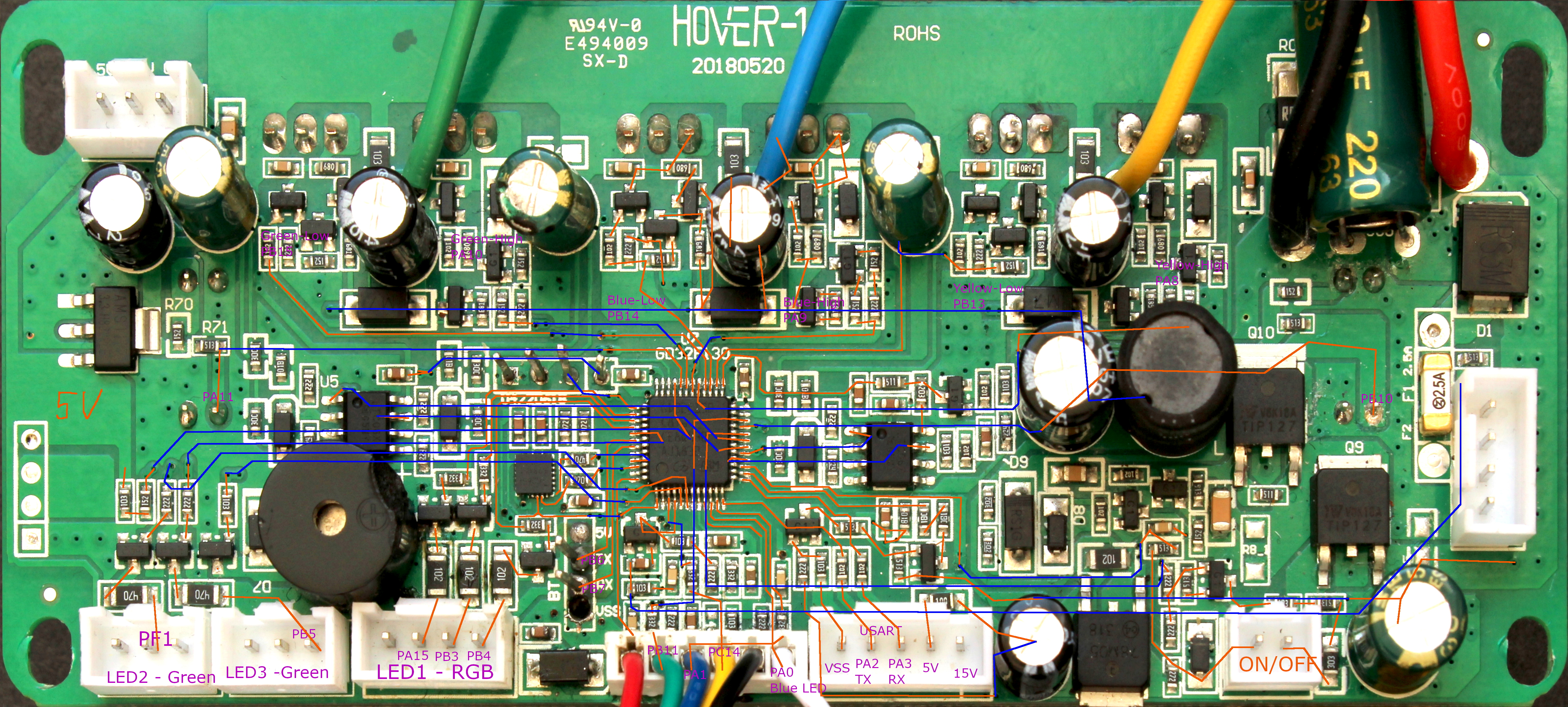
The autodetect results show PA7 for two different pins, this should not be possible by my software:

#define PHASE_A PA7
...
#define CURRENT_DC PA7

@llms3555 please post the complete log of the autodetect :-)

We have already a defines_2-1-13.h and hall and phase have been detected correctly by my autodetect:

#define PHASE_CURRENT_G PB1 // robo from pin tracing photo, maybe wong order
#define PHASE_CURRENT_B PB0
#define PHASE_CURRENT_Y PA7

But the rest ist wrong:

//#define BUZZER PA5

//#define VBATT P??
#define CURRENT_DC PA7
#define SELF_HOLD PA4
//#define BUTTON P??

@llms3555 can you confirm that your board is the same as in #38 ?

Then this bianry should already spin forward and backwards: https://github.com/RoboDurden/Hoverboard-Firmware-Hack-Gen2.x/blob/main/BinariesToTest/hoverboard%202.1.13%20master%20Dummy.bin

@AILIFE4798
Copy link

Itotal and phasea use same comparator
so i think he is lazy and did not used autodetect just traced manually

@RoboDurden
Copy link
Owner

This new Hover-1
grafik
is not exactly like the Gen2.1.13
grafik

The OnOff/BUTTON header is now directly beside the hall header and the dcdc step down components are different.

Should i assign a new layout number ?

@llms3555 please publish full autodetect log output here.

@llms3555
Copy link
Author

Disculpa la demora el tablero numero 38 es casi el mismo pero no totalmente tiene más conectores, cambian la posición del conector y el firmware de prueba 2.1.13 funciona las ruedas giran hacia atrás y adelante, prende el led azul del frente del hoverboard, también probe el el firmware (hoverboard 2.1.8 master Uart.bin) el pitido suena bien y prende el led de encendido en verde el problema de ese es que no hace nada en la conexión uart utilice el código testspeed con una esp32 y lo conecte por conexión uart pero no hace nada solo funciona el uart en el autodtect.

@RoboDurden
Copy link
Owner

RoboDurden commented Feb 21, 2024

Deepl:

Sorry for the delay the board number 38 is almost the same but not completely has more connectors, change the position of the connector and test firmware 2.1.13 works the wheels rotate back and forth, turns on the blue led on the front of the hoverboard, also test the firmware (hoverboard 2.1.8 master Uart.bin) the beep sounds good and turns on the green power led the problem with that one is that it does nothing in the uart connection use the testspeed code with an esp32 and connect it by uart connection but it does nothing only the uart works in the autodtect.

dumny.bin does not have uart support. You need to compile with RemoteUart in config.h

@llms3555
Copy link
Author

A entiendo que firmware funcionaria para conexion uart ???

@RoboDurden
Copy link
Owner

I will upload 2.1.13_Uart.bin tomorrow.

@llms3555
Copy link
Author

Entiendo, entonces esperaré hasta mañana. Agradezco mucho su tiempo y su ayuda. ¡Muchas gracias!

@RoboDurden
Copy link
Owner

@llms3555 , Lots of 2.13 binaries to test: https://github.com/RoboDurden/Hoverboard-Firmware-Hack-Gen2.x/tree/main/BinariesToTest

Only hoverboard 2.1.13 single PA2PA3-UartBus id0.bin and hoverboard 2.1.13 single PA2PA3-UartBus id1.bin use the master-slave uart header:
grafik

The other uart/uartBus binaries

hoverboard 2.1.13 master Uart.bin
hoverboard 2.1.13 single UartBus id0.bin
hoverboard 2.1.13 single UartBus id1.bin

need to connect here:
grafik

Please give feedback what is working for you and what not.

@llms3555
Copy link
Author

Entiendo muchas gracias probare todos te aviso después como salieron los resultados.

@llms3555
Copy link
Author

Este codigo de arduino funcionara en mi version de hoverboard :
// Tested with Arduino Pro Mini 3.3V and Hoverboard-TX to pin 9 and Hoverboard-RX to pin 8
//
// PB6 (Hoverboard-TX) and PB7 (Hoverboard-RX) can handle 5V I/O-Level :-)
//
// please share feedback to https://github.com/RoboDurden/Hoverboard-Firmware-Hack-Gen2.x

#define ESP32 // comment out if using Arduino
#define _DEBUG // debug output to first hardware serial port
//#define DEBUG_RX // additional hoverboard-rx debug output
//#define REMOTE_UARTBUS

#define SEND_MILLIS 100 // send commands to hoverboard every SEND_MILLIS millisesonds

#include "util.h"
#include "hoverserial.h"

#ifdef ESP32
#define oSerialHover Serial1 // ESP32
#else
#include <SoftwareSerial.h> // not compatible with RCReceiver because of interrupt conflicts.
SoftwareSerial oSerialHover(9,8); // RX, TX
#define oSerialHover Serial // Arduino
#endif
SerialHover2Server oHoverFeedback;

void setup()
{
#ifdef _DEBUG
Serial.begin(115200);
Serial.println("Hello Hoverbaord V2.x :-)");
#endif

#ifdef ESP32
// Serial interface, baud, RX GPIO, TX GPIO
// Note: The GPIO numbers will not necessarily correspond to the
// pin number printed on the PCB. Refer to your ESP32 documentation for pin to GPIO mappings.
HoverSetupEsp32(oSerialHover,19200,1,3);
#else
HoverSetupArduino(oSerialHover,19200); // 8 Mhz Arduino Mini too slow for 115200 !!!
#endif

pinMode(LED_BUILTIN, OUTPUT);
}

unsigned long iLast = 0;
unsigned long iNext = 0;
unsigned long iTimeNextState = 3000;
uint8_t wState = 1; // 1=ledGreen, 2=ledOrange, 4=ledRed, 8=ledUp, 16=ledDown , 32=Battery3Led, 64=Disable, 128=ShutOff
uint8_t iSendId = 0; // only ofr UartBus

void loop()
{
unsigned long iNow = millis();
digitalWrite(LED_BUILTIN, (iNow%2000) < 500);
//digitalWrite(39, (iNow%500) < 250);
//digitalWrite(37, (iNow%500) < 100);

int iSpeed = 3 * (ABS( (int)((iNow/20+100) % 400) - 200) - 100); // repeats from +300 to -300 to +300 :-)
int iSteer = 1 * (ABS( (int)((iNow/400+100) % 400) - 200) - 100); // repeats from +100 to -100 to +100 :-)
//int iSteer = 0;
//iSpeed /= 10;
//iSpeed = 200;
//iSpeed = iSteer = 0;

if (iNow > iTimeNextState)
{
iTimeNextState = iNow + 3000;
wState = wState << 1;
if (wState == 64) wState = 1; // remove this line to test Shutoff = 128
}

boolean bReceived;
while (bReceived = Receive(oSerialHover,oHoverFeedback))
{
DEBUGT("millis",iNow-iLast);
DEBUGT("iSpeed",iSpeed);
//DEBUGT("iSteer",iSteer);
HoverLog(oHoverFeedback);
iLast = iNow;
}

if (iNow > iNext)
{
//DEBUGLN("time",iNow)

#ifdef REMOTE_UARTBUS
  switch(iSendId++)
  {
  case 0: // left motor
    HoverSend(oSerialHover,0,CLAMP(iSpeed + iSteer,-1000,1000),wState);  // hoverboard will answer immediatly on having received this message ...
    break;
  case 1: // right motor
    HoverSend(oSerialHover,1,-CLAMP(iSpeed - iSteer,-1000,1000),wState);  // hoverboard will answer immediatly on having received this message ...
    iSendId = 0;
    break;
  }
  iNext = iNow + SEND_MILLIS/2;
#else
  //if (bReceived)  // Reply only when you receive data
    HoverSend(oSerialHover,iSteer,iSpeed,wState,wState);
  
  iNext = iNow + SEND_MILLIS;

#endif
}

}

@RoboDurden
Copy link
Owner

So you are using hoverboard 2.1.13 master Uart.bin ?

@llms3555
Copy link
Author

Este estoy utilizando:
overboard 2.1.13 single PA2PA3-UartBus id1.bin

@RoboDurden
Copy link
Owner

This can not work if you do not remove the // from

//#define REMOTE_UARTBUS

@llms3555
Copy link
Author

A entiendo entos corregire eso.

@llms3555
Copy link
Author

PBRFIRMWARE2
PBRFIRMWARE
Ya empesaron a girar las llantas con el firmware:
hoverboard 2.1.13 single PA2PA3-UartBus id1.bin

Que comandos usaria para poder mover las llantas libremente.

@llms3555
Copy link
Author

!He descubierto cómo hacerlo! El hoverboard funciona perfectamente ahora. Aprecio enormemente tu esfuerzo y ayuda. ¡Gracias de verdad!

@RoboDurden RoboDurden changed the title Resultados de Autodetect Hover-1 Drive (Gen2.1.13.1) - Resultados de Autodetect Hover-1 Drive Feb 25, 2024
@llms3555
Copy link
Author

llms3555 commented May 5, 2024

Hola, una disculpa por la molestia, como podría programar en esp32 que tiene dos RX y TX para hacer que las dos llantas se sincronicen al mismo tiempo ya que las dos placas son maestro y como se controlar el tiempo de giro de la llanta.

@I-hate-2FA
Copy link

if you need only tx no rx then you can just set 2 same slave id and they will be synchronized
if you need rx then you need to wait for the board to respond before commanding new value
and English only issue thanks

@llms3555
Copy link
Author

llms3555 commented May 5, 2024

Funciona para también rotar el hoverboard ?

@RoboDurden
Copy link
Owner

The first rule of project Mayhem: you do not ask questions!

@llms3555
Copy link
Author

llms3555 commented May 5, 2024

Understood, I won't ask any more questions. I hope I haven't caused any inconvenience.

Sign up for free to join this conversation on GitHub. Already have an account? Sign in to comment
Labels
None yet
Projects
None yet
Development

No branches or pull requests

4 participants