-
Notifications
You must be signed in to change notification settings - Fork 19
Probe Compensation Note
The Monoprice MP Mini Delta 3d printer uses the nozzle and three (3) switches attached to the printer's build plate to implement a Z-probe function. This function is used to automatically calibrate the printer and to create its automatic bed leveling mesh.
It's a simple way to use the nozzle as a z-probe, but the probe's z offset varies with the probe's x,y position. Marlin firmware, though, assumes that the probe's z-offset is constant and knows nothing about this type of probe.
My thought was that we could modify Marlin firmware to more accurately model this printer's z-probe mechanism with the goal to improve the firmware's auto-calibration command (G33) and to improve its auto bed leveling command (G29). Here are some notes about the implementation.
[spoiler alert!]
It didn't work well -- only a marginal improvement. Definitely a work-in-progress.
The Monoprice MP Mini Delta 3d printer employs three (3) mechanical switches under its build plate to detect the nozzle's contact with the build plate. This ability gives the Mini Delta a means for automatic calibration and bed-leveling, by "tapping" the build plate to determine a height (z-axis) value. The technique is flawed, though, as the build plate tilts during the measurement process. Here we provide an extremely naive model of the measurement error associated with the "tapping" process. The reasoning is as follows:
-
Normally, the build plate rests on top of three micro-switches.
-
The nozzle presses on the build plate until any one of the three switches makes contact. At this point, the current z-axis position is the build plate height (for a given x and y position).
-
There are seven possible orientations of the build plate in which at least one switch is depressed. We make the (probably wrong) simplifying assumption that any swith is at one end of its travel or the other (i.e. the z-axis position at the location of the switch is either zero or its full travel position, nothing in-between).
-
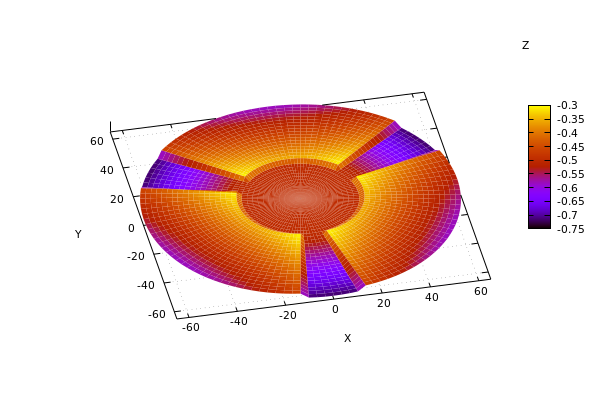
All three switches may make contact at the center (x,y = 0,0) of the build plate. The code below uses the radius of the probe's position to the center of the build plate to identify the "all three switches depressed" orientation of the build plate. Otherwise, the angle of the probe's position around the z-axis determines which of the remaining six orientations to use. There are three small regions where two of the three switches are depressed, and three remaining regions where only one of the three switches is depressed.
-
The code computes a plane for each orientation. Once the orientation is selected (from the probe's x, y position), the code computes the "expected" z-axis value, z = f(x,y), where f() is the equation of a plane for the selected orientation. This z value represents the measurement (height) error due to the tilt of the build plate.
-
Finally, we remove the switch travel from the result to normalize the (height) error to zero at (x:0,y:0). This last step is to mimic an "ideal" probe where the offset is uniform across the bed AND in such a way that is backward compatible with the existing calibration procedure for our firmware.
With a little assist from maxima, we can derive the plane equations and a probe model, that is, the action of the nozzle tapping on the build plate.
/* center area where 3 switches are depressed (radius, mm) */
/* Note: this value is more or less a "guess". */
/* ± area where 2 switches are depressed (angle, degrees) */
/* Note: this value is more or less a "guess". */
The three (3) bed switches are wired in parallel, so any single switch closure signals that the probe (i.e., the nozzle) has touched the bed. With only one switch closure the bed can be in one of three orientations. Here is a simple model of this only one switch closed idea.

Watching the printer, it's pretty clear that the "one switch closed, two switches fully open (no switch travel)" assumption is not correct -- that in somes cases, more than one switch may be closing (or close to closing). To approximate this condition, we use bed orientations that include 1, 2, or 3 switch closures in the model. Of course, this too is not correct since any one switch closure signals that the probe has touched the build plate. The hope here is that including all orientations that have at least one switch closure provides a better model than the simple model. Here is the improved model.
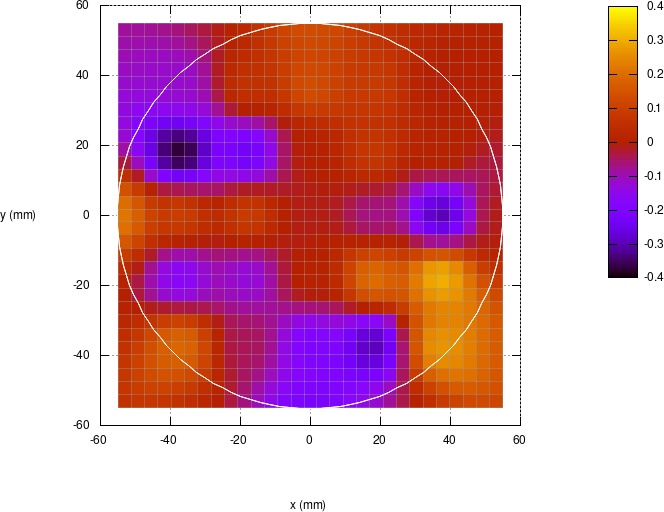
We test the firmware's auto-calibration and the probe compensation on a 3d printer fitted with a glass plate. We use the AUTO_CALIBRATE.gcode command in the setup_gcode directory on the micro SD card. This command performs the G33 auto-calibration plus the G29 auto bed leveling, and then uses the custom G29 C1 to fit a plane to the existing bed level data. The output of these commands is written to the CALIBRAT.TXT file on the micro SD card.
In the first test, the M111_S128.gcode disables the probe compensation.
/setup_gcode/M502_FACTORY.gcode    ; restore to factory settings
/setup_gcode/M111_S128.gcode       ; debug, disable probe compensation
/setup_gcode/AUTO_CALIBRATE.gcode  ; writes results to /CALIBRAT.TXT
 |
 |
bed level probe |
least squares plane fit |
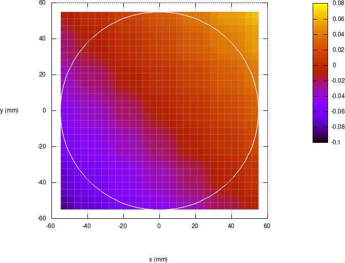
One would expect that the plot of the bed (with compensation disabled) to look something like the plot of the improved probe model. A quick visual comparison of the two plots shows only a "hint" of similarity. Since the printer under test has a glass print surface, we'd expect that the true bed is actually some kind of tilted plane. The least squares fit of a plane to the data indicates that the bed is slightly tilted from the lower left to the upper right. When printing, though, this does not seem to be the case.
/setup_gcode/M502_FACTORY.gcode    ; restore to factory settings
/setup_gcode/AUTO_CALIBRATE.gcode  ; writes results to /CALIBRAT.TXT
 |
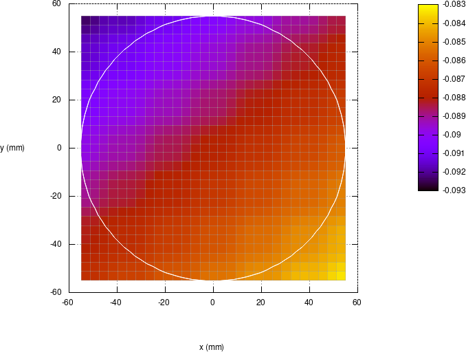 |
bed level probe |
least squares plane fit |
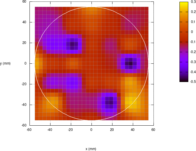
Using the probe compensation during the calibration procedure provides slightly more uniform bed level data, but the results are marginal at best. Again with a glass print surface, we'd expect this bed level probe plot (with probe compensation) to be some kind of tilted plane. The least squares fit of a plane to the data shows the tilt of the bed now from upper left to lower right, and this tilt is more in keeping with our experience when actually printing.
So far, the results are disappointing -- and a bit confusing. The measurements across the bed are inconsistent, but repeatable. Likewise, the calibration data are mediocre, but the machine prints quite well and reliably (on our sample of three machines). So, what gives?
Clearly, the model developed for the probe compensation is lacking. Perhaps this model can be improved further, but I think improving the probe compensation is only part of an overall solution. Perhaps changes to the calibration process (avoid probing problem areas on the bed) could minimize errors introduced by the bed probe and improve the calibration results. Also, considering the bed level data, we could employ some kind of post-processing of the data (e.g. least squares plane fit) to generate a consistent and more accurate bed level mesh. Hopefully the combination of these techniques will lead to better results.
So we have some avenues for further experimentation.
