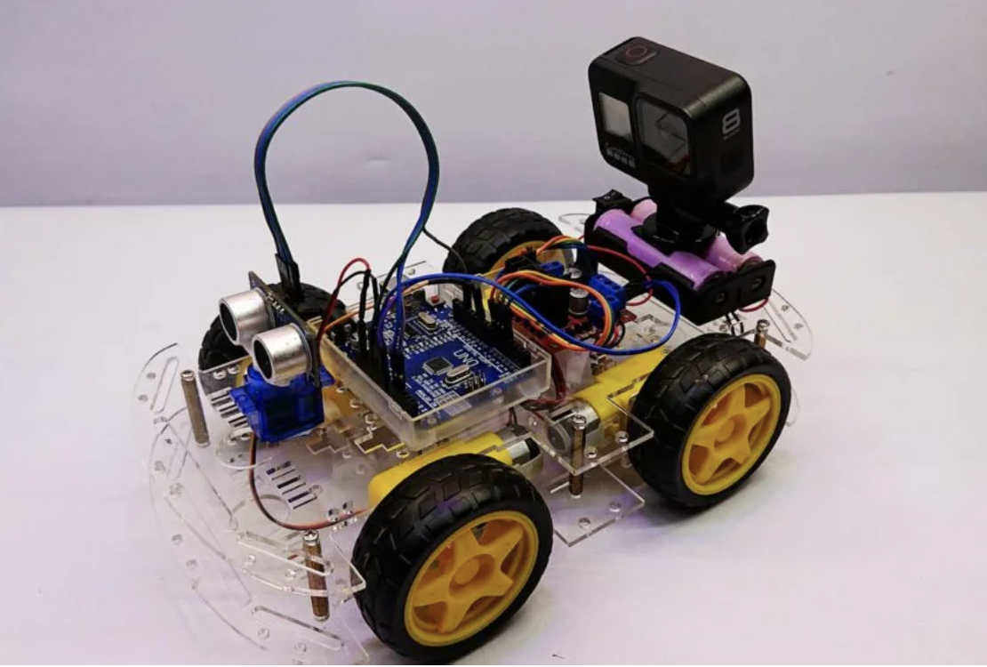
- Arduino Uno or compatible board
- 4-wheel chassis kit with DC motors
- L298N motor driver module
- Ultrasonic sensor (HC-SR04)
- SG90 servo motor
- Jumper wires
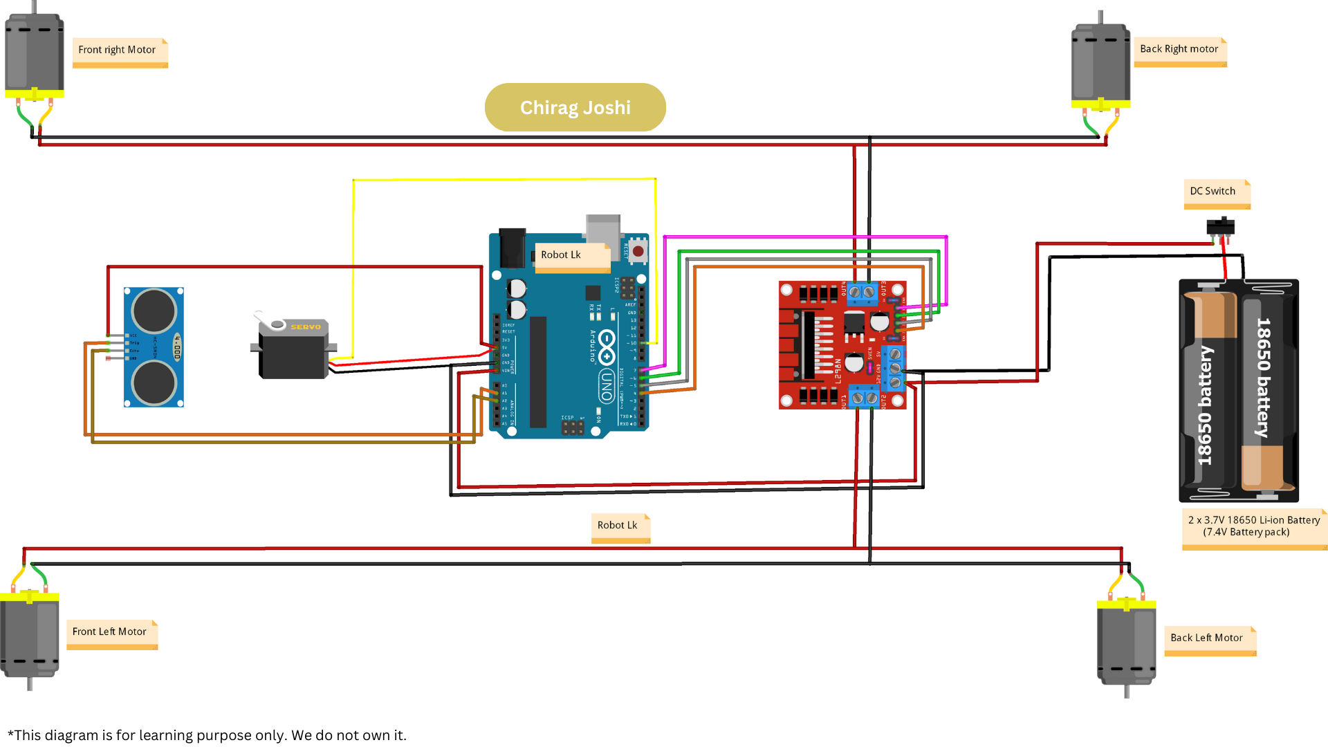
- Connect the two right motor Red wires to the “OUT4” terminals on the L298N motor driver.
- Connect the two right motor Black wires to the “OUT3” terminals on the motor driver.
- Connect the two left motor Black wires to the “OUT2” terminals on the motor driver.
- Connect the two left motor Red wires to the “OUT1” terminals on the motor driver.
- Connect the IN1 pin of the motor driver to digital pin D4 on the Arduino.
- Connect the IN2 pin of the motor driver to digital pin D5 on the Arduino.
- Connect the IN3 pin of the motor driver to digital pin D6 on the Arduino.
- Connect the IN4 pin of the motor driver to digital pin D7 on the Arduino.
- Connect the Signal (Orange Wire) from the servo motor to a digital pin D10 on the Arduino.
- Connect the VCC (Red Wire) from the servo motor to the 5V pin on the Arduino.
- Connect the GND (Brown Wire) from the servo motor to the GND pin on the Arduino.
- Connect the VCC (power) pin of the ultrasonic sensor to the 5V pin on the Arduino.
- Connect the GND (ground) pin of the sensor to the GND pin on the Arduino.
- Connect the TRIG (trigger) pin of the ultrasonic sensor to Analog pin A1 on the Arduino.
- Connect the ECHO pin of the sensor to another Analog pin A2 on the Arduino.
- Connect the Red wire (+) of the battery holder to the 12V In of the L298N Motor Driver and to the VIN Pin of the Arduino board.
- Connect the Black wire (-) of the battery holder to the GND In of the L298N Motor Driver and to the GND Pin of the Arduino board.
Here is a simple example of how to control the robot using the ultrasonic sensor to avoid obstacles: