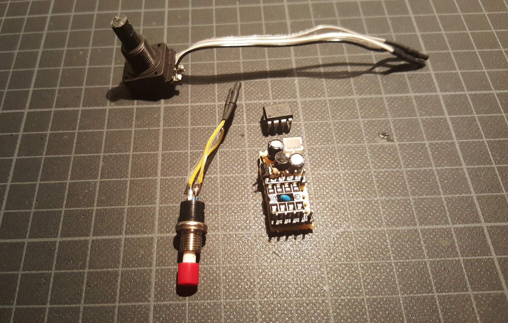
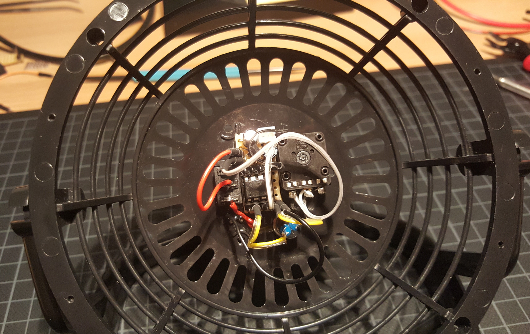
ATtiny85 based fan controller I built into a small USB powered desk fan. Uses ATTinyCore.
- added speed control per potentiometer
- added JST PH lipo battery connector to fan, crimped JST connector onto original USB cable
- voltage dependent lowest speed control (stalled motor prevention)
- burst start (stalled motor prevention)
- timer shuts off fan after a while
- push button resets timer / starts fan
- low voltage protection / start prevention
The fan in my project is driven by a brushless external rotor motor. The original controlling circuit is enclosed and I decided to not brake it open.
Some characteristics of the motor:
- two wires
- only spins in one direction (nothing happens when polarity is reversed)
- spins faster when voltage is increased
I've searched around the web and found a few discussions debating if it's ok to switch such a motor on the low side. Some say it wouldn't be optimal. In this project i'm switching the fan on the high side with a PNP transistor without problems. I didn't try low side switching.
To make the hack as simple as possible I first tried only using a BJT with a potentiometer. That works too, especially at full power. At lower speeds though the transistor just acts like a resistor and heats up. I didn't want that.
The first attempt with a PWM signal from the ATtiny produced an audible whine. This was using the regular 500 Hz PWM signal of the ATtiny / Arduino.
Setting TCCR0B the following way resulted into a 32 kHz PWM frequency. The whine was gone. This came at the expense of not being able to use delay() and millis() anymore. _delay_ms() of <util/delay.h> can be used instead but has limitations. To get 32 kHz the system clock must be 8 MHz. At 1 MHz the PWM signal would be 4 kHz.
TCCR0B = TCCR0B & 0b11111000 | 0b001;

In 3c958a0fc336c8cd7b6e249cedf1eaad32e0c821 I changed the 32 kHz TCCR0B PWM to a custom PWM using TIMER1. In depth details can be found in chapter "12. 8-bit Timer/Counter1" of the ATTiny datasheet.
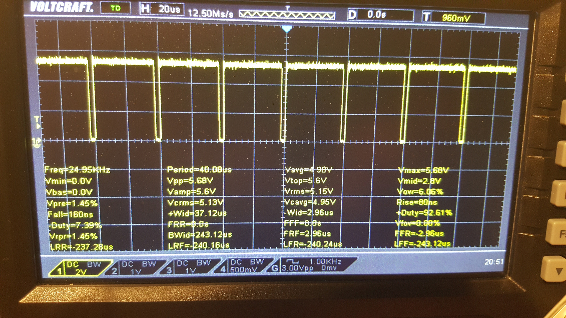
The following lines set up a 25 kHz PWM signal with 50% duty cycle on the physical pin 7 (OC1A). The system clock is 1 MHz.
TCCR1 &= 0xF0;      // turn off timer clock / reset all prescaler bits (some are set by default)
TCCR1 |= (1<<CS10); // no prescaler

OCR1C = 40; // this is how far the counter goes before it starts over again (255 max)
OCR1A = 20; // 50% of OCR1C

// turn it on
TCCR1 |= (1<<COM1A1);                 // OC1x cleared on compare match. Set when TCNT1 = $00. Inverted OC1x not connected.
// high and low time inverted:
//TCCR1 |= (1<<COM1A1) | (1<<COM1A0); // OC1x Set on compare match. Cleared when TCNT1= $00.  Inverted OC1x not connected.

// turn off
TCCR1 &= ~(1<<COM1A1 | 1<<COM1A0);
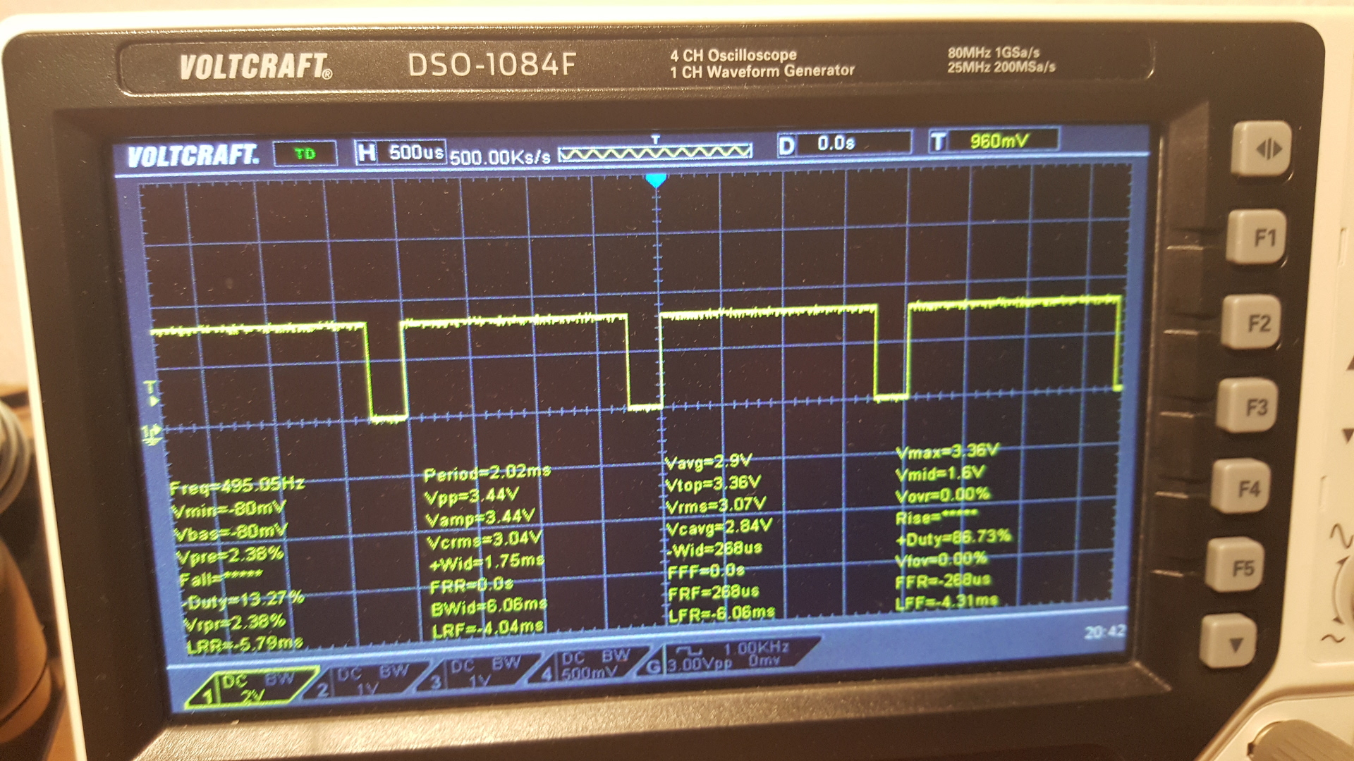
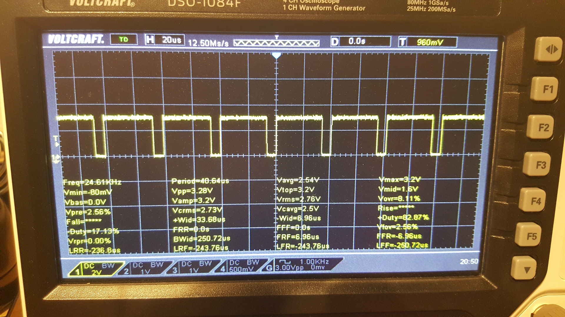
Besides the 25 kHz PWM frequency these traces also demonstrate that the lowest fan speed is changed depending on the measured voltage. The fan is driven when the pin is low.
3V:
5V: