Area represents a set of Gateways that belong to a single administrative group, e.g. belong to a single customer.
For each Area you can set:
- Name of the area.
- Region that determines behaviour of LoRaWAN Gateways in this area.
- Administrators responsible for this area.
- Slack Channel where status alerts shall be published.
- Log Ignored? indicates whether uplink frames from unknown and ignored nodes shall be logged as Received Frames
The server can be connected to one or more LoRaWAN gateways. All gateways act as one distributed antenna, common to all Networks:
- The server receives device uplinks from all gateways that received the signal, regardless to which Network does the device belong.
- Downlinks are them sent to the gateway that indicated best RSSI (Received Signal Strength Indication).
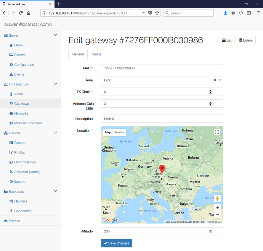
For each LoRaWAN gateway you can set and view its physical parameters:
- MAC address of the gateway
- Area, where this gateway belongs to.
- TX Chain identifies the gateway "radio chain" used for downlinks (usually 0).
It shall correspond to a
radio_x(e.g.radio_0) withtx_enable: truein gateway'sglobal_conf.json. - Antenna Gain (dBi) can be set to ensure the TX Power + Antenna Gain is below the maximal allowed Equivalent Isotropic Radiated Power (EIRP) for the given Network.
- Description for your convenience.
- Location and Altitude of the gateway
For the status:
- Alerts that may need your attention:
disconnectedwhen no UDP packet has been received from the gateway for more than 20 sec
- IP Address shows the gateway endpoint as viewed by the the server
- Last Alive contains a timestamp of the last received pull request. A gateway is considered dead if it didn't sent anything for more than 60 seconds.
- Last GPS contains a timestamp when the gateway last had a precise timing information from its GPS receiver.
- Last Report shows a timestamp of the last status report
- Network Delay graph shows network (LAN) delay between the gateway and the server
measured during the
PULL_RESPsequence. Note this requires packet_forwarder v3.0 or higher. The graph may not be updated when there is no LoRa traffic. - Transmissions graph shows how much did the gateway transmit in past hour. This is useful to monitor regulatory compliance.
The gateway power is always a minimum of TX Power and (max EIRP - Antenna Gain).
The server can handle one or more networks. Each Network configuration covers:
- Network Identifier used to create DevAddr for newly joined nodes
- LoRaWAN Regional Parameters, including additional frequencies (channels)
To correctly define the Regional Parameters you should review the specification "LoRaWAN Regional Parameters v1.0.2" or the suggested Default Regional Configuration for your region.
On the General tab you can set:
- Name of the network.
- NetID of the network. Private networks should use 000000 or 000001.
- Region that determines the LoRaWAN regional characteristics that cannot be modified.
- Coding Rate is always "4/5".
- RX1/RX2 Join Delay defines the JOIN_ACCEPT_DELAY1 and JOIN_ACCEPT_DELAY2.
- RX1/RX2 Delay defines the RECEIVE_DELAY1 and RECEIVE_DELAY2.
- Gateway Power (dBm) defines a default transmission power for downlinks.
The US 902-928MHz region allows a Private Hybrid mode introduced by Multitech. This is useful when you want to split the radio spectrum to 8 different sub-bands, but it requires custom device firmware.
On the ADR tab you can set the default parameters of your devices, i.e. how do the devices initially behave, without receiving any ADR command:
- Max EIRP (dBm) used in your region. For each region it is defined in the "Data Rate and End-device Output Power encoding" section.
- Max Power defines the first item in the "TX Power Table"
- Min Power defines the last item in the "TX Power Table"
- Max Data Rate defines the highest DR (lowest SF) supported by channels in this network. Additional Channels may specify a different value.
- Initial Duty Cycle is a number 0-15, where 0 means no restrictions;
- Initial RX1 DR Offset defines the offset between the uplink data rate and the downlink data rate used to communicate with the end-device on the first reception slot (RX1).
- Initial RX2 DR defines the data rate for the second reception slot (RX2). See the "Receive windows" section.
- Initial RX2 Freq defines the default frequency in the RX2 receive window.
The Max Data Rate is not always he last item (lowest SF) in the "TX Data rate table". Not all channels (frequencies) are allowed to use all data rates, for example in EU868 the default channels use SF12/125 to SF7/125 only. The SF7/250 is allowed for the 867.3 MHz channel only and FSK for 867.7 MHz only.
The device-specific ADR parameters can be set in the Device Profile ADR settings.
On the Channels tab you can set:
- Initial Channels enabled in your devices. This stall include a
comma-separated list of intervals, e.g.
0-2for EU or0-71for US. - Channels define a list of additional channels sent to the device during
Join (CFList)
- Frequency (MHz) defines the channel frequency
- Min Data Rate defines the lowest data rate allowed on this channel. If not specified, equals to 0.
- Max Data Rate defines the highest data rate allowed on this channel. If not specified, equals to the global value on the ADR tab.
Class B and Class C devices support multicast. Multiple devices can be configured to listen for downlinks targeted to a given DevAddr, so the same frame can be received by a group of devices. See also the Introduction.
To define a multicast channel you need to set:
- DevAddr of the channel; this must not collide with any Node address.
- Profiles that have this multicast configured.
- NwkSKey and AppSKey
- FCnt Down is the broadcast frame counter.