This project involves creating an environmental monitoring system using an SHT20 temperature and humidity sensor, an MQ-137 ammonia sensor, an LCD display, and Blynk for IoT integration.
- SHT20 Sensor: Measures temperature and humidity.
- MQ-137 Sensor: Measures ammonia levels in the air.
- LiquidCrystal_I2C: LCD display for showing sensor data.
- Blynk: Connects the system to the Blynk IoT platform for data logging and remote monitoring.
Wire.h: For I2C communication.LiquidCrystal_I2C.h: For interfacing with the LCD.SHT2x.h: For reading data from the SHT20 sensor.BlynkSimpleEsp32.h: For connecting to Blynk using an ESP32.WiFi.h: For WiFi connectivity.
graph TD;
    A[Start] --> B[Initialize components]
    B --> C[Connect to Blynk]
    C --> D[Check connection]
    D -- Connected --> E[Read SHT20 sensor data]
    D -- Not Connected --> F[Retry connection]
    E --> G[Check read success]
    G -- Success --> H[Read MQ-137 sensor data]
    G -- Failure --> I[Display error message on LCD]
    H --> J[Calculate heat index]
    J --> K[Categorize heat index]
    K --> L[Display data on LCD]
    L --> M[Send data to Blynk]
    M --> N[Delay 1 second]
    N --> E
- Serial Communication: Initialize at 115200 baud rate.
- I2C Communication: Initialize using
Wire.begin(). - SHT20 Sensor: Initialize and check status.
- LCD: Initialize and turn on the backlight.
- Blynk: Connect to Blynk using provided credentials and WiFi details.
- readMQ137(): Reads the analog value from the MQ-137 sensor and converts it to ppm.
- calculateHeatIndex(float temperature, float humidity): Converts temperature to Fahrenheit and calculates the heat index.
- categorizeHeatIndex(float hi): Categorizes the heat index into safety levels.
- displaySensorData(): Reads sensor data, calculates heat index, displays all values on the LCD, and sends data to Blynk. Also prints data to the serial monitor.
- setup(): Initializes all components and connects to Blynk.
- loop(): Continuously reads and displays sensor data and sends data to Blynk at regular intervals.
- Setup: Initializes serial communication, I2C, sensors, LCD, and Blynk.
- Loop: Reads and displays sensor data every second, and sends data to Blynk.
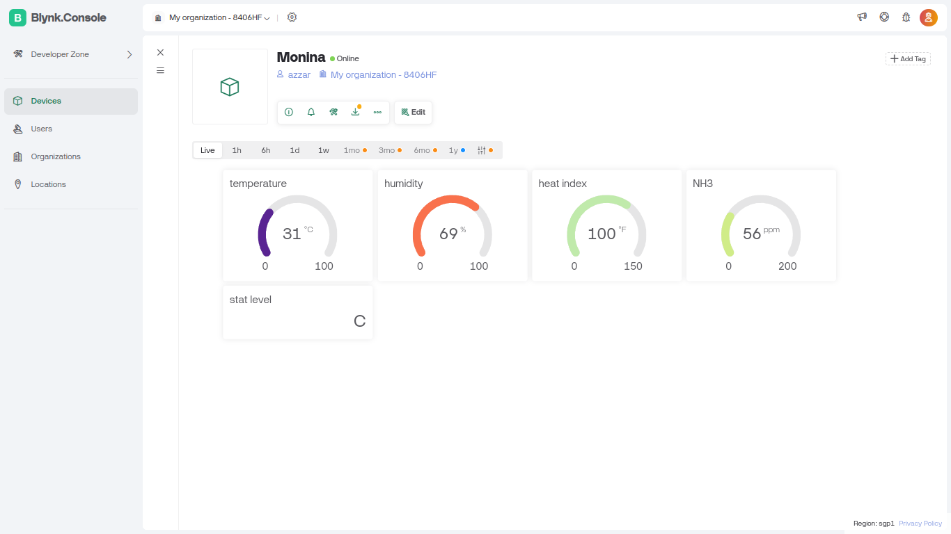
- Monitor the temperature, humidity, and ammonia levels in a laboratory, with remote data access via Blynk.
- Use the system in a greenhouse to ensure optimal growing conditions and remotely monitor the data.
- Install the system in a kitchen to monitor air quality and potential ammonia leaks, with IoT integration for alerts.
Calibrate the MQ-137 sensor for accurate ppm readings. The conversion formula in the code is a simplified version and may need adjustments based on your specific setup and calibration data.
If the SHT20 sensor fails to read, the system will display an error message on the LCD and print it to the serial monitor.
You can add more sensors or modules by expanding the I2C bus and updating the code accordingly. Additionally, more data feeds can be added to Blynk.
- ESP32 board
- SHT20 sensor
- MQ-137 sensor
- LCD display with I2C interface
- WiFi module (if not built-in)
- Connecting wires
- Arduino IDE
- Required libraries:
Wire.h,LiquidCrystal_I2C.h,SHT2x.h,BlynkSimpleEsp32.h,WiFi.h - Blynk account and credentials
- Connect the hardware components: Follow the sensor and LCD pin configurations.
- Install the Arduino libraries: Add the required libraries to your Arduino IDE.
- Configure Blynk: Replace placeholder credentials with your Blynk template ID, authentication token, and WiFi details.
- Upload the code: Load the provided code onto your ESP32 board.
- Monitor the output: View the readings on the LCD and the serial monitor for debugging, and check data logs on Blynk.
figure: