This page contains detailed instructions on building a module and flashing it with the latest firmware. Following these instructions will allow you to communicate with compatible inverters.
You find the full User_Manual here
Currently, the following inverters are supported:
Hoymiles Inverters
| Status | Serie | Model | comment |
|---|---|---|---|
| ✔️ | MI | 300, 600, 1000/1200/ |
4-Channel is not tested yet |
| ✔️ | HM | 300, 350, 400, 600, 700, 800, 1000?, 1200, 1500 | |
| ✔️ | HMS | 350, 500, 800, 1000, 1600, 1800, 2000 | |
| ✔️ | HMT | 1600, 1800, 2250 | |
| TSUN | TSOL-M350, TSOL-M400, TSOL-M800/TSOL-M800(DE) | others may work as well (need to be verified). | |
| 🟡 | HERF | (supported) |
- Overview
- Compatiblity
- Things needed
- Wiring things up
- Flash the Firmware on your Ahoy DTU Hardware
- Connect to your Ahoy DTU
- MQTT command to set the DTU without webinterface
- Used Libraries
- ToDo
Solenso Inverters:
- SOL-H350
To build your own AhoyDTU, you only need a few things. Remember that the maker community is always developing new and innovative options that we may not have covered in this readme.
Start with an ESP32 or ESP8266 (not recommended), and combine it with an NRF24L01+ breakout board for HM-series inverters. To communicate with a HMS or HMT inverter you need to use a CMT2300A radio module. Other ESP boards with at least 4MBytes of ROM may also be suitable.
Note for NRF24 radio module: Make sure to choose an NRF24L01+ module that includes the '+' in its name. This is important because we need the 250kbps features that are only available in the plus-variant.
Attention: The NRF24L01+ can only communicate with the MI/HM/TSUN inverter. For the HMS/HMT it is needed to use a CMT2300A!
| Parts | Price |
|---|---|
| D1 ESP8266 Mini WLAN Board Microcontroller | 4,40 € |
| NRF24L01+ SMD Modul 2,4 GHz Wi-Fi Funkmodul (not for HMS/HMT) | 3,45 € |
| CMT2300A 868/915MHz (E49-900M20S) | 4,59 € |
| 100µF / 10V Capacitor Kondensator | 0,15 € |
| Jumper Wire Steckbrücken Steckbrett weiblich-weiblich | 2,49 € |
| Total costs | 10,34 € / 11,48 € |
To future-proof your setup and use our sister project OpenDTU, we recommend investing in an ESP32 board with two CPU cores. Additionally, you can use a NRF24L01+ module with an external antenna as a radio for superior performance and compatibility with upcoming developments.
| Parts | Price |
|---|---|
| ESP32 Dev Board NodeMCU WROOM32 WiFi | 7,90 € |
| NRF24L01+ SMD Modul 2,4 GHz Wi-Fi Funkmodul (not for HMS/HMT) | 3,45 € |
| CMT2300A 868/915MHz (E49-900M20S) | 4,59 € |
| 100µF / 10V Capacitor Kondensator | 0,15 € |
| Jumper Wire breadboard female-female | 2,49 € |
| Total costs | 13,99 € / 15,13 € |
Beware of fake NRF24L01+ modules that use rebranded NRF24L01 chips (without the +). An example of this can be found in Issue #230 (#230). If you have any additional examples of fake chips, please share them with us and we will add the information here.
Users have reported improved connections and longer range through walls when using these modules. The "E01-ML01DP5" module is a 2.4 GHz wireless module that utilizes the nRF24L01+PA+LNA RF module and features an SMA-K antenna connector. The product includes an HF cover, but please note that it does not come with an antenna.
To achieve the best results, stabilize the Vcc power by using a capacitor and do not exceed the 'LOW' Amplifier Power Level. Users have reported good connections over 10m through walls and ceilings when using the Amplifier Power Level 'MIN'. It's important to remember that bigger is not always better.
If you are using the NRF24 directly on the ESP board, make sure to set the transmission power to the lowest possible level (this can be adjusted later in the web interface). Using a high transmission power can potentially cause problems. The ESP board's built-in controller has limited reserves in case both WiFi and nRF are transmitting simultaneously. If you are using additional interfaces, such as a display, the reserves will be further reduced.
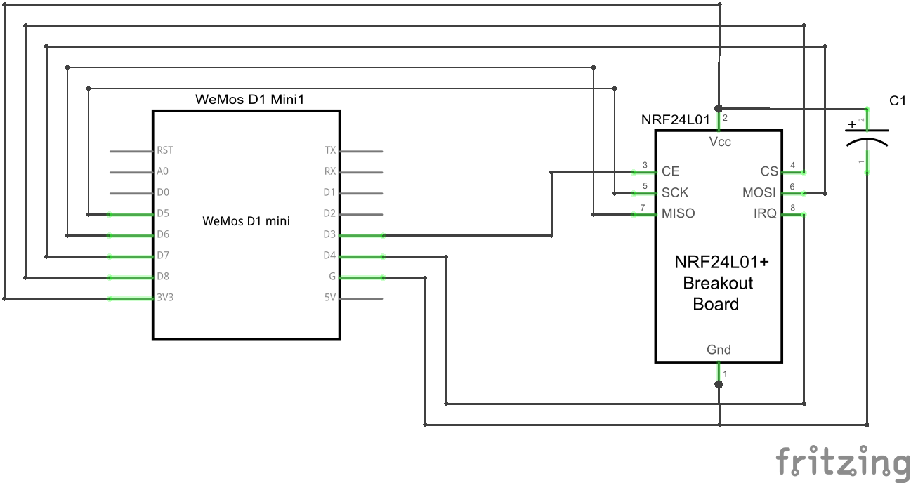
The NRF24L01+ radio module is connected to the standard SPI pins:
- SCLK (Signal Clock),
- MISO (Master In Slave Out) and
- MOSI (Master Out Slave In)
These pins need to be configured in the config.h.
Additional, there are 3 pins, which can be set individual:
- CS (Chip Select),
- CE (Chip Enable) and
- IRQ (Interrupt)
These pins can be changed from the /setup URL.
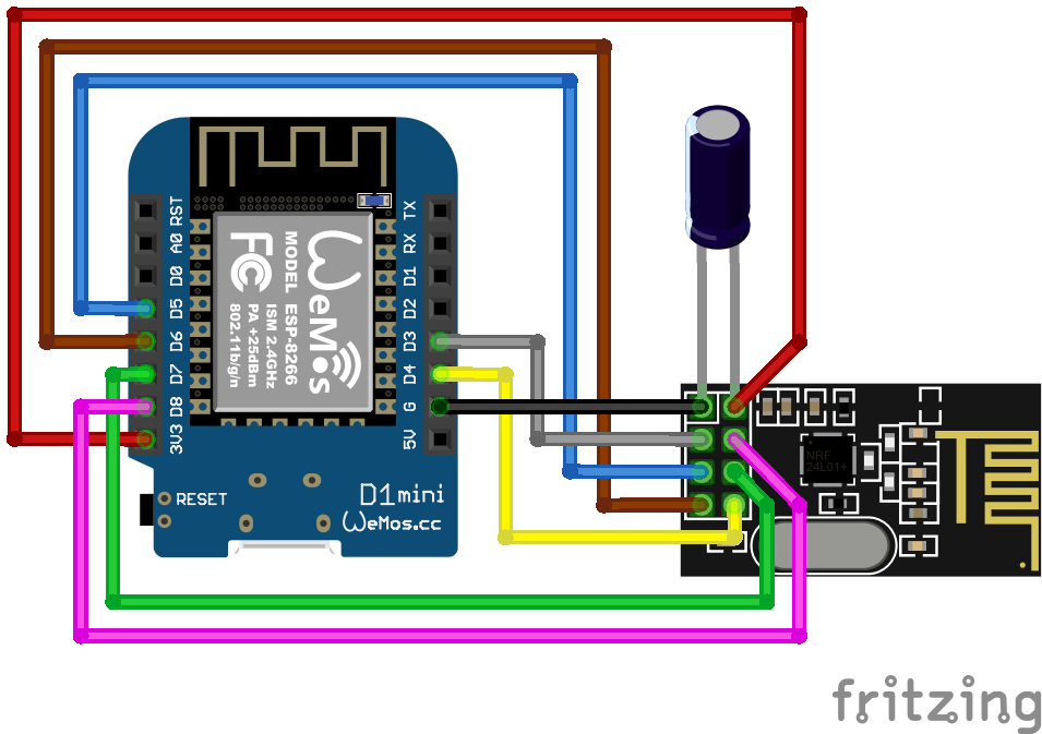
This is an example wiring using a Wemos D1 mini.
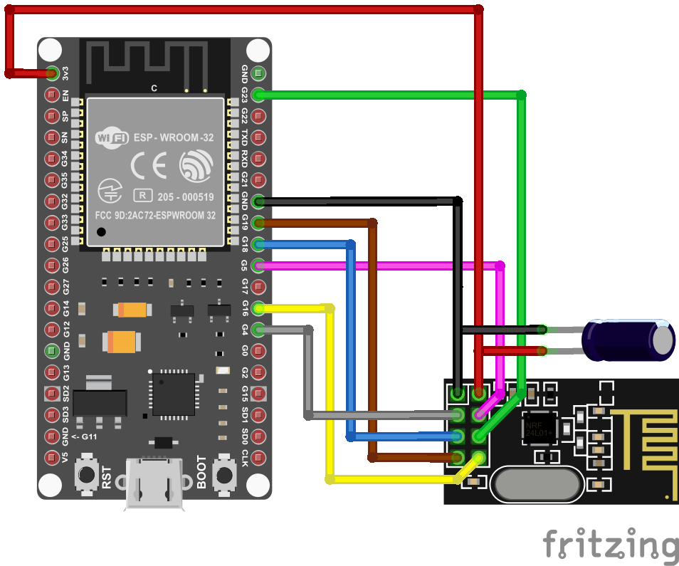
This is an example wiring using a NodeMCU V3.


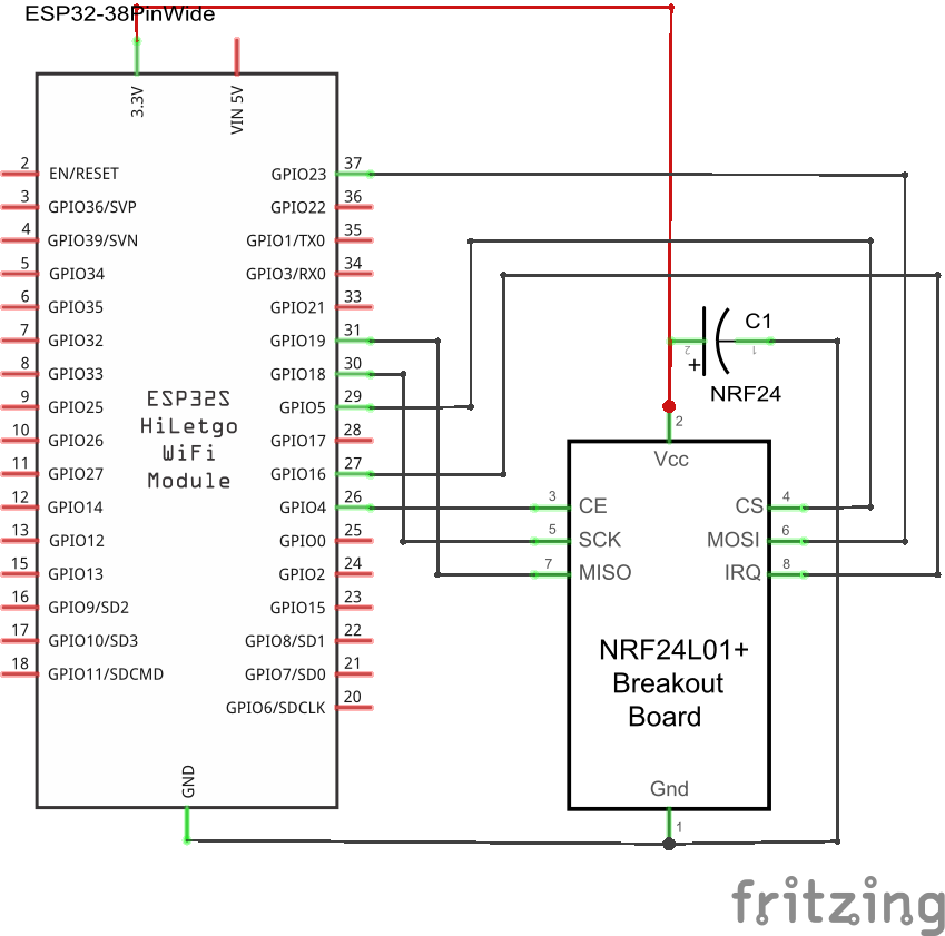
Example wiring for a 38pin ESP32 module
CS, CE, IRQ must be set according to how they are wired up. For the diagram above, set the 3 individual GPIOs under the /setup URL as follows:
CS   D1 (GPIO5)
CE   D2 (GPIO4)
IRQ  D0 (GPIO16 - no IRQ!)
IMPORTANT: Starting from development version 108/release 0.6.0, MISO, MOSI, and SCLK are also included. For most ESP32 boards, the default settings are correct on new installations. However, it is not possible to configure these pins for ESP82xx boards, as they cannot be moved elsewhere.
If you are upgrading an existing installation, you may notice that the pins are set to '0' in the web GUI, which will prevent communication with the NRF module. To resolve this, set MISO=19, MOSI=23, SCLK=18 in the settings. This is the correct default for most ESP32 boards. For ESP82xx, simply saving the settings without changes should suffice. Save and reboot.
After preparing your hardware, you must flash the Ahoy DTU Firmware to your board. You can either create your own firmware using your configuration or use one of our pre-compiled generic builds.
Are you ready to flash? Then go to next Step here.
The easiest step for you is to flash online. A browser MS Edge or Google Chrome is required. Here you go
This information is for those who wish to configure and build their own firmware.
The code is provided as a PlatformIO project and can be compiled using the PlatformIO Addon. The PlatformIO Addon is supported by Visual Studio Code, AtomIDE, and other IDEs. If you do not wish to compile your own build, you can use one of our pre-compiled binaries.
This information suits you if you just want to use an easy way.
- download the flash-tool nodemcu-pyflasher
- download latest release bin-file from ahoy_
- open flash-tool and connect the target device to your computer.
- Set the correct serial port and select the correct *.bin file
- click on "Flash NodeMCU"
- flash the ESP with the compiled firmware using the UART pins or
- repower the ESP
- the ESP will start as access point (AP) if there is no network config stored in its eeprom
- connect to the AP (password:
esp_8266), you will be forwarded to the setup page - configure your WiFi settings, save, repower
- check your router or serial console for the IP address of the module. You can try ping the configured device name as well.
Once your Ahoy DTU is running, you can use the Over The Air (OTA) capabilities to update your firmware.
! ATTENTION: If you update from a very low version to the newest, please make sure to wipe all flash data!
- install esptool.py if you haven't already.
- download and extract the latest release bin-file from ahoy_
cd ahoy_v<XXX> && cp *esp32.bin esp32.bin- Perhaps you need to replace
/dev/ttyUSB0to match your acual device in the following command. Execute it afterwards:esptool.py --port /dev/ttyUSB0 --chip esp32 --before default_reset --after hard_reset write_flash --flash_mode dout --flash_freq 40m --flash_size detect 0x1000 bootloader.bin 0x8000 partitions.bin 0x10000 esp32.bin - Unplug and replug your device.
- Open a serial monitor (e.g. Putty) @ 115200 Baud. You should see some messages regarding wifi.
Once everything is wired and the firmware is flashed, it is time to connect to your Ahoy DTU.
Once connected to your computer, you can open a serial console to get additional information. This can be useful for troubleshooting, as well as simply to get information about the converted values read from the inverter(s).
After you have successfully flashed and powered up your Ahoy DTU, you can access it from your browser.
If your Ahoy DTU was able to log on to the configured WiFi network, it will try to obtain an IP address from your local DHCP server (in most cases this is your router).
If it cannot connect to your configured network, it will provide its own WiFi network that you can to for further configuration.
The WiFi SSID (the WiFi name) and password are pre-configured and are set to SSID "AHOY-DTU" and password "esp_8266" by default.
The Ahoy DTU will keep this network open for a certain amount of time (default is 60sec). If nothing connects to it and the time expires, it will retry to connect to the configured network, and so on.
If you are connected to your local network, just find out the IP address used or try the default name http://ahoy-dtu/. In most cases, your router will give you a hint.
If you connect to the WiFi the Ahoy DTU opens in case it could not connect to any other Network, the IP-Address of your Ahoy DTU is http://192.168.4.1/. Just open the IP-Address in your browser.
The web interface has the following capabilities:
- Live data (values updated every 5 seconds) Click on the title/name/alarm for more actions.
- Webserial (Debug)
- Settings (System Config, Network, Protection, Inverter, NTP Server, Sunrise/Sunset, MQTT, Display Config)
- Update (Over The Air Update)
- System (status about the modules)
To take control of your Ahoy DTU, you can directly call one of the following sub-pages (e.g. http://ahoy-dtu/setup or http://192.168.4.1/setup ).
| page | use | output | default availability |
|---|---|---|---|
| /logout | logout the user from webinterface | yes | |
| /reboot | reboots the Ahoy DTU | yes | |
| /system | show system inforamtion | yes | |
| /live | displays the live data | yes | |
| /save | yes | ||
| /erase | erases the EEPROM | yes | |
| /factory | resets to the factory defaults configured in config.h | yes | |
| /setup | opens the setup page | yes | |
| /metrics | gets live-data for prometheus | prometheus metrics from the livedata | no - enable via config_override.h |
| /api | gets configuration and live-data in JSON format | json output from the configuration or livedata | yes |
| Name | version | License |
|---|---|---|
ESP8266WiFi |
1.0 | LGPL-2.1 |
DNSServer |
1.1.1 | LGPL-2.1 |
SPI |
1.0 | LGPL-2.1 |
Hash |
1.0 | LGPL-2.1 |
EEPROM |
1.0 | LGPL-2.1 |
ESPAsyncWebServer |
1.2.3 | LGPL-3.0 |
| ESPAsyncTCP | 1.2.2 | LGPL-3.0 license |
| Time | 1.6.1 | ? |
| RF24 | 1.4.8 | GPL-2.0 license |
| espMqttClient | ? | MIT license |
| ArduinoJson | 6.21.3 | MIT license |
| GxEPD2 | 1.5.2 | GPL-3.0 license |
| U8g2_Arduino | 2.35.9 | BSD-2-Clause |