Skip to content
New issue

Have a question about this project? Sign up for a free GitHub account to open an issue and contact its maintainers and the community.

By clicking “Sign up for GitHub”, you agree to our terms of service and privacy statement. We’ll occasionally send you account related emails.

Already on GitHub? Sign in to your account

SDM120c with esp8266 #13

Closed
crywolf87 opened this issue Dec 20, 2017 · 49 comments
Closed

SDM120c with esp8266 #13

crywolf87 opened this issue Dec 20, 2017 · 49 comments
Labels

Comments

@crywolf87
Copy link

Hi
I can't link ESP8266 with Sdm120C , using interface Rs485.(
whatsapp image 2017-12-20 at 18 58 44

Please find the SCHEMA attached.

whatsapp image 2017-12-20 at 18 58 22

Could you please tell me how to modifie the sketch to use this configuration? (Vedi schema).

An other favour. What's the difference between hardware serial and software serial?

Many thanks for your support

@reaper7
Copy link
Owner

reaper7 commented Dec 20, 2017

difference for me are stability, no read error (if hardware serial is selected).

note: if serial is set on pins 13/15 then sometimes esp do not wake up, because pin 15 must be low on esp bootup process. so, for test try to set other pins first time

120c default baud rate is 2400? You must change this in setup

SDM<2400, YOUR_RX_PIN_NUMBER, YOUR_TX_PIN_NUMBER> sdm; 

@crywolf87
Copy link
Author

image
I have setup the value and choose pin 13 e 12 for serial port but the sdm not comunicate with esp822.
this is part of configuration.

@reaper7
Copy link
Owner

reaper7 commented Dec 20, 2017

esp8266 do not have hardware uart pin on 12 :)
in this configuration You can not use HARDWARE_SERIAL option

  1. install software serial library
  2. remove or comment first line from your sketch:
#define USE_HARDWARESERIAL

3 try again

@crywolf87
Copy link
Author

The software serial library just instal.

How pin can be assigned?

Pin D0 and D5 ?

but the response are

�[1;0HVoltage: nanV

Current: nanA
Power: nanW
Frequency: nanHz
�[1;0HVoltage: nanV
Current: nanA
Power: nanW
Frequency: nanHz

@reaper7
Copy link
Owner

reaper7 commented Dec 20, 2017

you can stay on 12 13, if not working swap wires
leds on your rs485 converter blinks? debug with leds, you can see if some data is tx and/or rx

@crywolf87
Copy link
Author

the led tx and rx blink both for four and repeat

@reaper7
Copy link
Owner

reaper7 commented Dec 20, 2017

that's good, this mean esp send to sdm and sdm reply...
you are sure if baud is propertly installed, check on your sdm

@crywolf87
Copy link
Author

the sdm is setup like : 2400 parity none id 1

@reaper7
Copy link
Owner

reaper7 commented Dec 20, 2017

I don't know what's wrong :(

try add this line after last reading (frequency)

Serial.print(sdm.getErrCode());

@crywolf87
Copy link
Author

error n° 4

this on sdm.h

#define SDM_ERR_TIMEOUT 4 //timeout

#define READING_STEP_CNT 4

@reaper7
Copy link
Owner

reaper7 commented Dec 20, 2017

so, esp do not receive an answer

but You say both converter leds blinks in the same time,

for me You have wrong connected rx wire between converter and esp (not to declared pin)

@crywolf87
Copy link
Author

If inver the wire rx between convert and esp blink only RxD.

`#include <SDM.h> //import SDM template library

#define ASCII_ESC 27

char bufout[10];

#define YOUR_TX_PIN D7
#define YOUR_RX_PIN D6

//SDM<2400, YOUR_TX_PIN, YOUR_RX_PIN> sdm;
SDM<2400, 12, 13> sdm; //SDM120T baud, rx pin, tx pin, dere pin(optional for max485)
//SDM<4800, 13, 15> sdm; //SDM220T baud, rx pin, tx pin, dere pin(optional for max485)
//SDM<9600, 13, 15> sdm; //SDM630 baud, rx pin, tx pin, dere pin(optional for max485)
//or without parameters (default from SDM.h will be used):
//SDM<> sdm;

void setup() {
Serial.begin(115200); //initialize serial
sdm.begin(); //initialize SDM220 communication baudrate
}

void loop() {

sprintf(bufout,"%c[1;0H",ASCII_ESC);
Serial.print(bufout);

Serial.print("Voltage: ");
Serial.print(sdm.readVal(SDM220T_VOLTAGE), 1); //display voltage
Serial.println("V");

delay(100);

Serial.print("Current: ");
Serial.print(sdm.readVal(SDM220T_CURRENT), 1); //display current
Serial.println("A");

delay(100);

Serial.print("Power: ");
Serial.print(sdm.readVal(SDM220T_POWER), 1); //display power
Serial.println("W");

delay(100);

Serial.print("Frequency: ");
Serial.print(sdm.readVal(SDM220T_FREQUENCY), 1); //display frequency
Serial.println("Hz");
Serial.print(sdm.getErrCode());

delay(3000); //wait a while before next loop
}`

@reaper7
Copy link
Owner

reaper7 commented Dec 20, 2017

I don't know, sorry.
If you have some rs232 to usb converter then connect as spy (only gnd and rx line) and connect first to gpio12 and check if any data is transmitted, then connect to gpio13 and check this line have data too

@crywolf87
Copy link
Author

I'll do some other tests tomorrow.

it's very strange because even with sdm staccato flash both rx and tx

@crywolf87
Copy link
Author

I didn'thave a rs232<>usb converter for test the tx and rx split.
I have an other converter rs48 but this have a 2 pin de and re.
How to connect this.
I must configure another pin to de e re ?

The conver

@reaper7
Copy link
Owner

reaper7 commented Dec 21, 2017

I've never tested this kind of converters (with de/re pins)
but You must change init to this:

SDM<2400, 12, 13, YOUR_ESP_PIN_NUMBER_FOR_DE_RE> sdm;

and connect de re pins together to this esp pin

@reaper7
Copy link
Owner

reaper7 commented Dec 21, 2017

one more thing...
look at this line:
https://github.com/reaper7/SDM_Energy_Meter/blob/master/SDM.h#L18

this is max waiting time for read completly reply from sdm
maybe it is too small value (500ms) for 2400baud
please first (before you change converter) try to increase this value to 1000...1500

@ngalfas
Copy link

ngalfas commented Dec 21, 2017

Hi, i am testing with an SDM530 Modbus.

I confirm that the Wemos D1 does not wake up when SoftwareSerial is connected to D7-D8 pins. To have it working i remove D8 cable, i press reset button on Wemos PCB, i put back the D8 cable and then i can see the data on the serial monitor.

Changing the MAX_MILLIS_TO_WAIT does not make any difference, i am also on 2400 bauds, this is the default setting on SDM530 from factory.

I am testing with a MAX485 module, thank you for your library.

@crywolf87
Copy link
Author

Hi hgalfas
can you put the scheme and sketch that used to w1mos, and type of MAX485 module (picture) please.

thanks in advantace

@crywolf87
Copy link
Author

Incredible, workkkkkkkkkkkk.

@ngalfas
Copy link

ngalfas commented Dec 21, 2017

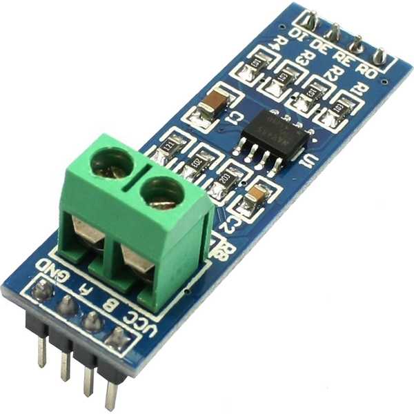
MAX485 module https://www.aerial.net/shop/imageslarge/IOT-RS485_main.jpg
VCC to 5V Wemos
GND to GND
DE and RE pins connected together and then to D6 Wemos
RO to D7 Wemos
DI to D8 Wemos

I used the sdm_simple example from the library with this config
`//SDM<2400, 13, 15> sdm; //SDM120T baud, rx pin, tx pin, dere pin(optional for max485)
//SDM<4800, 13, 15> sdm; //SDM220T baud, rx pin, tx pin, dere pin(optional for max485)
//SDM<9600, 13, 15> sdm; //SDM630 baud, rx pin, tx pin, dere pin(optional for max485)
//or without parameters (default from SDM.h will be used):
//SDM<> sdm;

//lib init when Software Serial is used:
SDM<2400, 13, 15, 12> sdm; //baudrate, rx pin, tx pin, dere pin(optional for max485)`

As i said, my meter comes with 2400 bauds from factory so i left it like this.

AND BE WARNED: the ESP8266 on WEMOS D1, DOES NOT WAKE UP when SoftwareSerial is connected to D7-D8 pins. To have it working i remove D8 cable, i press reset button on Wemos PCB, i put back the D8 cable and then i can see the data on the serial monitor.

@crywolf87
Copy link
Author

thanks ngalfas :-)

I have a question.
If I set up the baudrate and pin in the sketch, with

SDM<2400, 12, 13, YOUR_ESP_PIN_NUMBER_FOR_DE_RE> sdm;
will the parameters into the file SDM.h be ignored?

thenks

@reaper7
Copy link
Owner

reaper7 commented Dec 21, 2017

Yes, default value(s) will be overwriten with your value from sketch.

How do you solve your problem?

@crywolf87
Copy link
Author

I don't know :-(

how pin support the serial similar D7 eD8 ?

the w1mos Crash,

@crywolf87
Copy link
Author

wdt reset
load 0x4010f000, len 1384, room 16
tail 8
chksum 0x2d
csum 0x2d
v0c897c37
~ld

@ngalfas
Copy link

ngalfas commented Dec 22, 2017

i am also having crashes with the example. works only for 2-3 minutes, then crashes

�[1;0HVoltage: 222.95V
Current: 0.53A
Power: 87.57W
Total Power: 88.70W
Total Power: 0.00Wh
Frequency: 50.01Hz
�[1;0HVoltage: 222.75V
Current: nanA
Power:
Exception (0):
epc1=0x40202b6c epc2=0x00000000 epc3=0x00000000 excvaddr=0x00000000 depc=0x00000000

ctx: sys
sp: 3ffffbf0 end: 3fffffb0 offset: 01a0

stack>>>
...........................
<<<stack<<<

ets Jan 8 2013,rst cause:2, boot mode:(1,6)

ets Jan 8 2013,rst cause:4, boot mode:(1,6)

wdt reset

Haven't looked in to it yet. I think it has to do with watchtimer.

@reaper7
Copy link
Owner

reaper7 commented Dec 22, 2017

check exception+stack with Arduino "ExceptionDecoder":
https://github.com/me-no-dev/EspExceptionDecoder

  • I personally do not use softwareserial, only hardwareserial (I do not use Serial.print... so standard uart on pins 1/3 is free)
  • Please check/replace your power source (voltage peaks, temporary drops), usb in some cases, may be not enough, especially if you also supply converter

@crywolf87
Copy link
Author

hi,
today I have tested the hardware serial with sdm_live page.ino.
the system work .
Now I verify the stability.

@ngalfas
Copy link

ngalfas commented Dec 22, 2017

Ok, the crashes on my side were from the PC-USB power source being unstable for both Wemos and MAX485.

When i powered it from a wall converter it never crashed again. I added a led lightup on every loop so i visually check it keeps running :)

@crywolf87
Copy link
Author

hi,
it's possible use sdm_simple with hardware serial ?
I would used sketck sdm_simple to look the sdm's indicators with a display.

I would like to use serial hardware because it works better than softserial
because the configuration of the sdm_live page is too complicated for me now,(
because I'm inexperienced with C at the moment) then I would like to use that sdm_simple though with harware serial.

@reaper7
Copy link
Owner

reaper7 commented Dec 23, 2017

yes, you can use hardware serial but you can't use "Serial.print" at the same time because hardware serial in this case is used to communicate with sdm

if You connect your sdm to standard esp hardware uart (pins 1/3) then
put at top of Your sketch:

#define USE_HARDWARESERIAL

and initialize lib only with Your baud (if You are using converter from first post):
SDM<2400> sdm;

@ngalfas
Copy link

ngalfas commented Dec 23, 2017

i am struggling for the whole day to make it work on TX/RX pins on Wemos D1 but i have no luck.
i disabled the builtin LED, i kept the same RE-DE pin, i made sure there is no serial monitoring in the sketch, but no luck.
The best i have come up with is that the ESP talks to the EASTRON through MAX485, i can see the COMM led lights on EASTRON, i see the "phone" icon on EASTRON stating there is Modbus communication, but there is no data posted on MQTT. I see the ESP posting MQTT with null values from EASTRON.

And if i switch to SoftSerial and change TX/RX pins, change the apprpriate lines in sketch, it works! but only for SoftSerial.

Here is the two types of calling for Hard or Soft Serial
//lib init when Hardware Serial is used:

#define USE_HARDWARESERIAL // place it BEFORE calling <SDM.h>
#include <SDM.h> //import SDM template library
SDM<4800, D6> sdm; //baudrate, dere pin(optional for max485), swap hw serial pins from 3/1 to 13/15

//lib init when Software Serial is used:
//#include <SDM.h> //import SDM template library
//SDM<4800, D7, D5, D6> sdm; //baudrate, rx pin, tx pin, dere pin(optional for max485) with SoftwareSerial

on HardwareSerial i even tried calling like
SDM<4800, D6, false> sdm; (Saw it like this on Github welcome page)
SDM<4800, D6> sdm;
SDM<4800> sdm;

@crywolf87
Copy link
Author

I have the similar problem.
I would read the sdm and post into telegram, but the data not arrived.

`#define USE_HARDWARESERIAL
#include <SDM.h>
SDM<2400, 14, false > sdm;
#define ASCII_ESC 27

char bufout[10];

WiFiClientSecure client;
UniversalTelegramBot bot(BOT_TOKEN, client);

#include <UniversalTelegramBot.h>
#include <WiFiClientSecure.h>
#include <DNSServer.h>
#include <WiFiManager.h>

void setup() {
//Serial.begin(115200); //initialize serial
sdm.begin(); //initialize SDM220 communication baudrate

WiFiManager wifiManager;
wifiManager.setSTAStaticIPConfig(IPAddress(192,168,1,99), IPAddress(192,168,1,1), IPAddress(255,255,255,0));
wifiManager.autoConnect("host", "passwd");

}

void loop() {
float tmpval;

sprintf(bufout,"%c[1;0H",ASCII_ESC);
//Serial.print(bufout);

// Serial.print("Voltage: ");
//Serial.print(sdm.readVal(SDM220T_VOLTAGE), 1); //display voltage
// Serial.println("V");
tmpval = (sdm.readVal(SDM120C_VOLTAGE), 2);

String msg = String (tmpval);
String message = "LA TENSIONE : ";
message.concat("\n");
message.concat("E ': ");
message.concat(msg);
message.concat("\n");
delay(1000);`

but the results is:

"LA TENSIONE"
"E : 2.00'"

I don't understand.

:-(

@reaper7
Copy link
Owner

reaper7 commented Dec 23, 2017

@crywolf87 tell me, what it is?

tmpval = (sdm.readVal(SDM120C_VOLTAGE), 2);

it should be:

tmpval = sdm.readVal(SDM120C_VOLTAGE);

@crywolf87
Copy link
Author

Now I have find the error.
Thank's

@reaper7
Copy link
Owner

reaper7 commented Dec 23, 2017

gentlemen, you have an additional uart (only tx) for debug (separate rs232 to usb is necessary)
On GPIO2 is Serial1:
https://arduino-esp8266.readthedocs.io/en/latest/reference.html#serial

@crywolf87
Copy link
Author

crywolf87 commented Dec 27, 2017

hi,
I have continued the test of sdm and esp8266.
The result in very positive.
Now if would to read more meters sdm120c, i can use this comand :

readVal(SDM220T_VOLTAGE, 0x01) //read voltage from node 1

and 0x02 to the second meters ?

like this post :
https://github.com/reaper7/SDM_Energy_Meter/issues/10

thank's

Davide

@reaper7
Copy link
Owner

reaper7 commented Dec 27, 2017

Yes, exactly

@crywolf87
Copy link
Author

How use the Serial1 ?
To monitor the information to serial1, is necessary a monitor serial (i.evan Duke: secure CRT?)

I have a PL2303_Prolific (rs232 <->usb ).
How to use?

thanks

@reaper7
Copy link
Owner

reaper7 commented Dec 30, 2017

GPIO2 is tx pin for Serial1
so, in setup set Serial1 speed:
Serial1.begin(115200);

and print your informations via
Serial1.print("some my debug data");

@crywolf87
Copy link
Author

but to see the "some my debug data" I use an external serial monitor or the arduino serial monitor?

@reaper7
Copy link
Owner

reaper7 commented Dec 30, 2017

if you can switch to PL2303_Prolific COM in arduino then use it,
Personally I use Termite app

@crywolf87
Copy link
Author

If I use the secure crt (emulator serial) how set the parametri?
8n1 ?.

I read the value when switch the serial to Arduino monitor serial.
Unfortunatly the line txt is not compresible

@reaper7
Copy link
Owner

reaper7 commented Dec 31, 2017

default is 8N1
please, read esp8266 arduino documentation:
http://esp8266.github.io/Arduino/versions/2.0.0/doc/reference.html#serial

@crywolf87
Copy link
Author

It's works.

The converter Rs232 is broken.

Thanks

@crywolf87
Copy link
Author

sorry I have added the 'readVal(SDM220T_POWER, 0x02) ' to read the power but didn't work.

ttmp = sdm.readVal(SDM120C_VOLTAGE); //firts meters
ctmp = sdm.readVal(SDM120C_CURRENT); //firts meters
ptmp = sdm.readVal(SDM120C_POWER, 0x02); //second meters
hztmp = sdm.readVal(SDM120C_FREQUENCY); // //firts meters.

@reaper7
Copy link
Owner

reaper7 commented Jan 16, 2018

Sorry I never test this option (with two meters at once), maybe someone else use this.
But when I set inside sdm menu id to 2 then reading from sketch (..., 0x02) works for me.

@crywolf87
Copy link
Author

crywolf87 commented Jan 19, 2018

The reader works with 2 meters at one.
If necessary set the delay for each reading (like 200ms).
I use the address decimal

ttmp = sdm.readVal(SDM120C_VOLTAGE, 2)

did you try the librarywith the node-red's program?

I try this metod to node-red, but i don't know use this library because I don't import the library to node-.

@marine1988
Copy link

i there i have 1 nodemcu 8266 and a rs485 i can´t read any values nan every time any help?

This issue was closed.
Sign up for free to join this conversation on GitHub. Already have an account? Sign in to comment
Labels
Projects
None yet
Development

No branches or pull requests

4 participants