Platform Configuration Instructions
![]() This document is a work-in-progress, so there are likely typos and sections that aren't very clear. If you have any questions, or something doesn't make sense, or if you have a suggestion, please open an issue or shoot us an email.
This document is a work-in-progress, so there are likely typos and sections that aren't very clear. If you have any questions, or something doesn't make sense, or if you have a suggestion, please open an issue or shoot us an email.
When preparing an AutoRally platform, there is some configuration that must be completed on the compute box and operator control station (OCS) laptop so that all of the devices can communicate. The following instructions will guide you through this process. Some steps are only required for the compute box or OCS, which is noted at the beginning of those steps.
![]() Due to distributed launch issues, we do not recommend that you use conda or pip environments on the compute box.
Due to distributed launch issues, we do not recommend that you use conda or pip environments on the compute box.
![]() These instructions assume you have an AutoRally chassis and compute box constructed, OCS laptop, and have completed the software setup instructions found in
These instructions assume you have an AutoRally chassis and compute box constructed, OCS laptop, and have completed the software setup instructions found in autorally/README.md on both the compute box and OCS machine.
- Install Tools
- Configure IP addresses and ssh permissions
- Clock synchronization setup (chrony and gpsd)
- Set roscore to auto start
- Set AutoRally udev rules
- Setup Compute Box Data Drive
- Change Power Button Behavior
- Disable Login and Lock Screen Password Prompts
- Setup on-board sensors
- Install M4api and Configure Cutoff Voltage
- Setup Cameras
- Configure XBees
- Configure GPS
- Configure Chassis Microcontroller
- Configure Compute Box Microcontroller
- Configure Runstop Microcontroller
- Configure and Calibrate IMU
- Configure GPU
- Configure Platform-Agnostic Launch System
- Verification
Install tools and software needed:
sudo apt install chrony gpsd-clients cutecom lm-sensors acpi indicator-multiload libopencv-dev
Install latest version of Arduino IDE and Teensyduino Software. You may have to put the Teensyduino installer in the arduino software folder (i.e. arduino-1.8.5/ not the Arduino/ folder in home) for it install successfully.
Install latest version of Nvidia Management Library Python bindings.
Uninstall the modem manager:
sudo apt remove modemmanager
For the ROS distributed launch system to work, your compute boxes and OCS laptops will need to have static IP addresses assigned and be on the same network. We suggest assigning in the 192.168.XXX.XXX range, but this is not a requirement.
Once you have static IP addresses assigned, follow these steps to enable ROS to SSH between your devices without requiring login credentials.
-
Ensure the the Ubuntu firewall is disabled:
sudo ufw disable -
Add all other devices (compute boxes and OCS laptops) to
/etc/hostson each computer. Each entry should look like this:192.168.<XXX>.<XXX> <hostname> -
For each computer (compute box and OCS laptop), create an SSH key, if it already doesn't have one:
ssh-keygen -t rsa -C "<your_email@example.com>" -
If you are setting up an AutoRally compute box, do the following for each OCS laptop
-
Copy the OCS laptop's key to your compute box:
ssh-copy-id <remote username>@<remote hostname> -
SSH into the OCS laptop:
ssh <remote username>@<remote hostname> -
Copy your key to that OCS laptop:
ssh-copy-id <your username>@<your hostname>
-
We use chrony to synchronize the clocks on all computers within a distributed ROS system. The robot acts as an NTP server, and all external machines synchronize their clocks to the robot's. The compute box on the robot synchronizes its clock to the reported GPS time coupled with the GPSs PPS signal using chrony and gpsd. GPS satellites are a stratum 0 clock, so the chrony server on the robot is configured as a stratum 1 clock.
Chrony and gpsd should already be installed.
By default, chronyd and gpsd will start automatically on boot. This must first be disabled so that the correct configuration can be used.
Disable chrony and gpsd on startup:
sudo systemctl disable chrony gpsd
Then run
sudo systemctl stop systemd-timesyncd
sudo systemctl disable systemd-timesyncd
sudo service chrony stop
sudo update-rc.d -f chrony remove
Reboot and verify that chrony is disabled by running
service --status-all | grep chrony
You should see the following in the output
[ - ] chrony
The apparmor module blocks chrony from performing time synchronization, so we disable chrony's profile from it:
sudo ln -s /etc/apparmor.d/usr.sbin.chronyd /etc/apparmor.d/disable/
sudo apparmor_parser -R /etc/apparmor.d/usr.sbin.chronyd
Verify the chrony profile is no longer under "enforced" by running
sudo apparmor_status
In autorally/autorally_util/, you will find two chrony configuration templates. The following list shows the lines you will need to complete to use these files:
- chronyClient.conf - this is the configuration file for OCS machines and any other computers in the system
-
server AUTORALLY_COMPUTE_BOX_HOSTNAME(line 47)- Add one of these lines, uncommented, with the correct hostname, for each AutoRally compute box.
-
initstepslew 10 AUTORALLY_COMPUTE_BOX_HOSTNAME(line 159)- Add one of these lines, with the correct hostname, for each AutoRally compute box.
-
cmdallow 192.168/16(line 260)- Make sure the partial IP address shown on this line matches the IP addresses on your local network.
-
- chronyServer.conf - this is the configuration file for compute boxes
-
allow 192.168/16(line 181)- Make sure the partial IP address shown on this line matches the IP addresses on your local network. This allows client to access this instance of chrony from the local network for time synchronization.
-
cmdallow 192.168/16(line 253)- Make sure the partial IP address shown on this line matches the IP addresses on your local network.
-
Add the following line to /etc/rc.local. Make sure to update the location of the chronyServer.conf file where required.
sudo chronyd -f [PATH_TO_CATKIN_WORKSPACE]/src/autorally/autorally_util/chronyServer.conf -r
Add the following line to /etc/rc.local. Make sure to update the location of the chronyClient.conf file where required.
sudo chronyd -f [PATH_TO_CATKIN_WORKSPACE]/src/autorally/autorally_util/chronyClient.conf -r
![]() You will need to restart the computer to start chrony with the new configuration.
You will need to restart the computer to start chrony with the new configuration.
Verify chrony is working by typing chronyc sources. The output from a configured compute box is shown below. Note that the local time sources GPS, PPS1, and PPS0 are shown. On an OCS machine, the local time sources should be the hostname of all compute boxes.

![]() This step is only needed for AutoRally compute boxes.
This step is only needed for AutoRally compute boxes.
In our distributed launch setup, the compute box on the vehicle acts as the 'master' for the ROS distributed launch. Automatically starting roscore when the machine starts automates a startup step.
Edit the /etc/rc.local file, and change the first line to: #!/bin/bash -e. Then, at the bottom of the file (before the line exit 0), add the following lines, substituting the paths for the specific compute box.
source /opt/ros/<ROS_VERSION>/setup.bash
source [PATH_TO_CATKIN_WORKSPACE]/devel/setup.bash
roscore&
Like this, the first line takes over std out to create a log file if you typo anything at /tmp/rc.local.log
#!/bin/bash -e
#
# rc.local
#
# This script is executed at the end of each multiuser runlevel.
# Make sure that the script will "exit 0" on success or any other
# value on error.
#
# In order to enable or disable this script just change the execution
# bits.
#
# By default this script does nothing.

exec 1>/tmp/rc.local.log 2>&1
source /opt/ros/melodic/setup.bash
source /home/autorally/catkin_ws/devel/setup.bash
roscore&

exit 0
Restart and verify that roscore has started by running
rostopic list
and seeing the output
/rosout
/rosout_agg
If you see ERROR: Unable to communicate with master! then roscore has failed to start.
Example rc.local file
Copy the AutoRally udev rules to the udev folder:
sudo cp [PATH_TO_CATKIN_WORKSPACE]/src/autorally/autorally_util/99-autoRally.rules \
/etc/udev/rules.d/
![]() This step is only needed for AutoRally compute boxes, and will create the folder where ROS logs will be stored.
This step is only needed for AutoRally compute boxes, and will create the folder where ROS logs will be stored.
-
Use gparted to create a new MSDOS partition table on the drive with a single, primary ext4 partition.
-
Add an entry to
/etc/fstabto tell the OS to mount the data drive to/media/datawhen the machine starts, by running this command:sudo echo "[PARTITION PATH] /media/data ext4 defaults 0 2" >> /etc/fstab -
Give your user access to the data drive by running this command:
sudo chown -R <username>:<username> /media/data
sudo mkdir /media/data
![]() This step is only needed for AutoRally compute boxes.
This step is only needed for AutoRally compute boxes.
Run the following command to change the power button's behavior to shutdown the computer without a dialog prompt.
gsettings set org.gnome.settings-daemon.plugins.power button-power shutdown
![]() This step is only needed for AutoRally compute boxes.
This step is only needed for AutoRally compute boxes.
![]() This step is only needed for AutoRally compute boxes.
This step is only needed for AutoRally compute boxes.
- Open System Settings
- For 16.04, click the User Accounts button. For 18.04, click Details, then Users.
- Click the Unlock button and enter your password when requested.
- Turn ON automatic login
- Open System Settings
For 16.04: 2. Click the Brightness and Lock button 3. Turn Lock off 4. Uncheck "Require my password when waking from suspend."
For 18.04: 2. Click Privacy, then Screen Lock. 3. Turn Automatic Screen Lock off.
![]() This step is only needed for AutoRally compute boxes.
This step is only needed for AutoRally compute boxes.
Clone or download the latest version of the nct6775 driver from groeck's GitHub account.
git clone https://github.com/groeck/nct6775.git ~/nct6775
Build and install this driver.
make && sudo make install
Add the following line to /etc/modules to tell Ubuntu to load the nct6775 driver on startup.
nct6775
After a system restart, the nct6775 driver should be loaded.
Scan system for sensors, answer yes to all questions
sudo sensors-detect
If you run the sensors command, you should see an entry for coretemp-isa-#### and an entry like nxt6791-isa-#### or nct6793-isa-####
iwconfig only shows link quality measures to the root user. In order for our software to get this information automatically, we must allow sudo iwconfig to be run without requiring the sudoers password. To do this, add the following line to /etc/sudoers through the sudo visudo editor.
<username> ALL=(root) NOPASSWD: /sbin/iwconfig
![]() This step is only needed for AutoRally compute boxes with the Mini-Box M4-ATX power supply.
This step is only needed for AutoRally compute boxes with the Mini-Box M4-ATX power supply.
To setup access to the M4-ATX powersupply, you'll need to install the M4API from mini-box.com
-
Clone or download and extract the archive of ktossell's m4api GitHub repository here
-
Open a new terminal in the extracted folder.
-
Make a build directory:
mkdir build cd build -
Configure the installation directory for cmake. One way to do this is to run
ccmake ..and change CMAKE_INSTALL_PREFIX to /usr. -
Install the API
make sudo make install -
Add the following line to the end of the sudoers file by running
sudo visudo<username> ALL=(root) NOPASSWD: /usr/bin/m4ctl -
Add udev permissions for the power supply.
sudo sh -c "echo 'SUBSYSTEM=="usb", ATTRS{idVendor}=="04d8", ATTRS{idProduct}=="d001", MODE="0666"' >> /etc/udev/rules.d/40-m4ctl.rules" -
With the power supply USB connected to the computer, run the following command to configure the cutoff voltage of the power supply using the m4ctl software that was just installed:
sudo m4ctl -config VIN_MIN_ON 18.5 sudo m4ctl -config VIN_MIN_START 18.5 -
Confirm the settings were saved:
sudo m4ctl -config VIN_MIN_ON
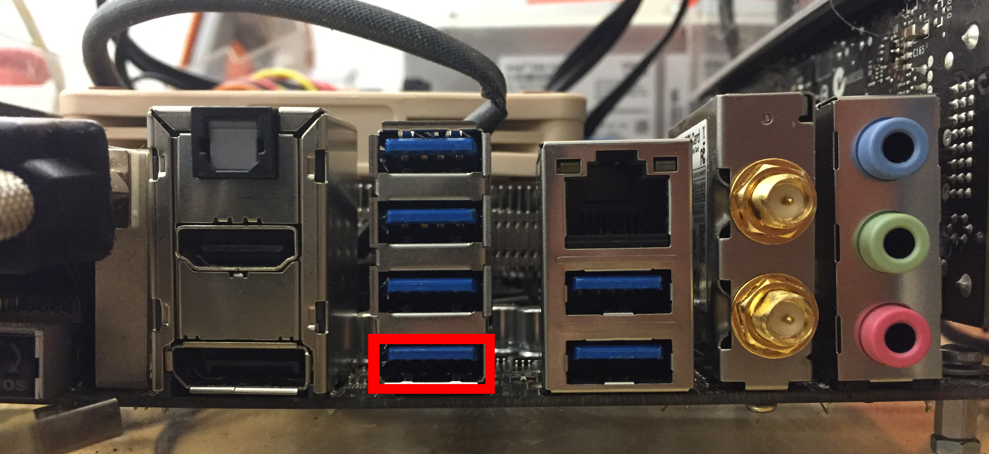
![]() It is suspected, though not thoroughly verified, that m4api will work with the ASUS Z87I-Deluxe motherboards ONLY when plugged into the lowest port of the 4-port USB-3.0 tower. See highlight in the image below.
It is suspected, though not thoroughly verified, that m4api will work with the ASUS Z87I-Deluxe motherboards ONLY when plugged into the lowest port of the 4-port USB-3.0 tower. See highlight in the image below.
![]() This step is for AutoRally compute boxes with USB3.0 cameras. If the platform is to use a Point Grey Flea 3 camera, install the FlyCapture2 SDK. If the platform is to use a FLIR Blackfly S camera, install the Spinnaker SDK.
This step is for AutoRally compute boxes with USB3.0 cameras. If the platform is to use a Point Grey Flea 3 camera, install the FlyCapture2 SDK. If the platform is to use a FLIR Blackfly S camera, install the Spinnaker SDK.
Install FlyCapture's dependencies with the following command:
sudo apt-get install libgtkmm-2.4-1v5 libatkmm-1.6-dev libcairomm-1.0-dev libgtkglext1-dev libgtkglextmm-x11-1.2-0v5 libgtkglextmm-x11-1.2-dev libglademm-2.4-1v5 libglademm-2.4-1v5 libglademm-2.4-dev libglade2-dev
Download the latest version of FlyCapture, 64-bit for your Ubuntu version, and install by executing the provided install script.
IMPORTANT: During installation select 'no' if asked about making a symlink to any version of libraw1394, 'yes' to all others.
You should now be able to connect a PointGrey camera into the machine and view it by running flycap.
Download the latest version of Spinnaker (selecting "Blackfly S" as the product family) for your version of Ubuntu. Extract the archive, and refer to the README sections 1.1 and 3 to install Spinnaker and its dependencies.
You should now be able to connect a FLIR camera and view a feed by running spinview.
Until this PR is merged, a fork of ROS's flir_camera_driver must be used.
cd ~/catkin_ws/src
git clone https://github.com/ebretl/flir_camera_driver.git
From PointGrey's Technical Application Note, Using Linux with USB 3.0
By default, Linux limits image capture to 2 MB. To capture images over 2 MB, extend the USBFS limit on how many buffers can be locked into the driver. This is done by updating the boot params in grub. You can set the memory limit until the next reboot, or set it permanently.
To set the maximum usbfs memory limit permanently:
-
Open the /etc/default/grub file in any text editor. Find and replace:
GRUB_CMDLINE_LINUX_DEFAULT="quiet splash"with this:
GRUB_CMDLINE_LINUX_DEFAULT="quiet splash usbcore.usbfs_memory_mb=1000" -
Update grub with these settings:
sudo update-grub -
Reboot and test a USB 3.0 camera using FlyCapture.
- Open the sudoers editor with
sudo visudo. Add the following lines to the end of the file.
Cmnd_Alias ARCAMSET = /bin/chmod -R 777 /dev/bus/usb/
<username> ALL=(root) NOPASSWD: ARCAMSET
- Write the file (Ctrl-O) and exit the editor (Ctrl-X).
- Open the "Startup Applications" utility.
- Select "Add".
- Enter a meaningful name (ie. Camera Permissions), and paste the following line in the "Command:" field, replacing "autorally" with your username, and ensuring that the path points to your cloned repo's location.
[PATH_TO_CATKIN_WORKSPACE]/src/autorally/autorally_util/setCameraPermissions.sh
- Click "Save" and close Startup Applications Preferences. You are done. Permissions will now be set when you log in.
- Download and install XCTU
![]() The rest of this step is for AutoRally compute boxes and if you are configuring a Runstop box.
The rest of this step is for AutoRally compute boxes and if you are configuring a Runstop box.
-
Connect all XBee radios to the computer and open the XBee's settings in XCTU.
-
Configure the XBee's settings as follows.
Xbee Coordinator settings (sits inside the Runstop box)
- NI (Node Identifier) - XBEECOORDINATOR1
- NO (Node Discovery Options) - 0
- DD (Device Type Identifier) - 70000
- BD (Baud Rate) - 230400 [8]
- AP (Api Enable) - API Without Escapes [1]
Xbee Node (inside compute box)
- CE (Routing/Messaging Mode) - Non-Routing Module [2]
- NI (Node Identifier) - XBEEPLATFORM1
- DD (Device Type Identifier) - 70000
- BD (Baud Rate) - 230400 [8]
- AP (Api Enable) - API Without Escapes [1]
 Each XBee needs to have a unique Node Identifier (NI) (ie. XBEECOORDINATOR1, XBEECOORDINATOR2, XBEEPLATFORM1, XBEEPLATFORM2, etc...)
Configuration instructions for the hemisphere Hemisphere R320 base station and Eclipse P303 rover.
Base station Power is provided by a 12V AC/DC converter connected to the base station power plug. Data comes from the Port A and B USB/serial connections on the device.
The base station outputs data on 2 USB ports, arGPSBasePortA, arGPSRoverPortB, connected to ports A and B, respectively, of the GPS, with appropriate definitions in the udev rules file. Port A is used to get position information from the base station in NMEA0183 messages, and port B is used to receive RTK corrections for broadcast to rovers in RTCM3 format. This assumes L1/L2, RTK, GLONASS activations on all devices and 20Hz on the rovers.
To configure the base station, connect via your program of choice to ports on the GPS device (cutecom is easy to use), and enter the following commands, with cr,lf line endings:
Port A: arGPSBasePortA
$JBAUD,115200
$JMODE,GPSONLY,NO
$JMODE,GLOFIX,YES
$JASC,GLGSV,1
$JASC,GPGSV,1
$JASC,GNGSA,1
$JASC,GPGST,1
$JASC,GPGNS,1
$JSAVE
To confirm the desired messages are being output, verify the response to $JSHOW,GP is:
$>JSHOW,GP,GNS,1.0,GSV,1.0,GST,1.0,GNGSA,1.0,GLGSV,1.0
Port B: arGPSBasePortB
$JBAUD,115200
$JMODE,base,yes
$JASC,RTCM3,1
$JRTK,5,1
$JSAVE
Power is supplied to the rover and antenna by a 3.3V supply. All power and data into and out of the rover goes through the 12pin GPS interface cable connected between the GPS box and the compute box.
The rover outputs data on 2 USB ports, arGPSRoverPortA and arGPSRoverPortB. Another port is dedicated to RTK input, arGPSRoverPortD. Each port should have an correcponding entry in the udev rules file. Port A is used to get position information from the base station as NMEA0183 messages, port B is used by gpsd for time synchronization, and port D is used to relay RTK corrections received from the base station to the rover. For gpsd to have the highest accuracy, the pps output form the rover is connected to the DCD pine of the port b serial to USB interface board along with a 10kohm resistor from pps line to ground. This configuration was taken from here.
![]() The default baud rate for ports A and B, 19200, and 9600 for port D. Once you change the baud of a port, such as using the command
The default baud rate for ports A and B, 19200, and 9600 for port D. Once you change the baud of a port, such as using the command $JBAUD,115200, the device will immediately switch to the new baud rate. To send the rest of the configuration commands, and save the configuration, you will need to close your connection and reopen with the new baud rate.
To configure the rover, connect a serial terminal program of choice to ports on the GPS device (cutecom is easy to use), and enter the following commands, with cr,lf line endings:
$JOFF
$JBAUD,115200
$JDIFF,BEACON
$JASC,PSAT,RTKPROG,1
$JASC,PSAT,RTKSTAT,1
$JMODE,GPSONLY,NO
$JMODE,GLOFIX,YES
$JASC,GLGSV,1
$JASC,GPGSV,1
$JASC,GNGSA,1
$JASC,GPGST,1
$JASC,GPGNS,20
$JSAVE
To confirm the desired messages are being output, verify the response to $JSHOW,GP is:
$>JSHOW,GP,GNS,20.0,GSV,1.0,GST,1.0,GNGSA,1.0,GLGSV,1.0
$JOFF
$JBAUD,115200
$JASC,GPGGA,1
$JASC,GPGLL,1
$JASC,GPGSA,1
$JASC,GPGST,1
$JASC,GPVTG,1
$JASC,GPZDA,1
$JSAVE
To confirm the desired messages are being output, verify the response to $JSHOW,GP is:
$>JSHOW,GP,GGA,1.0,GLL,1.0,VTG,1.0,GSA,1.0,ZDA,1.0,GST,1.0
Do not disconnect after configuring Port B and issuing $JSAVE.
Port D will be configured from Port B. Issue these commands while connected to Port B.
$JBAUD,9600,PORTD,SAVE
$JASC,RTCM3,1,PORTD
$JASC,PSAT,RTKPROG,1,PORTD
$JASC,PSAT,RTKSTAT,1,PORTD
$JSAVE
Issue the command $JSHOW and verify that the output matches that shown below. Note: $>JSHOW,POS does not have to show the same values as below. Note: the line $>JSHOW,DIFF,BEACON,NONE may show something other than NONE at the end
$>JSHOW,BAUD,115200
$>JSHOW,ASC,GPGGA,1.0
$>JSHOW,ASC,GPGLL,1.0
$>JSHOW,ASC,GPVTG,1.0
$>JSHOW,ASC,GPGSA,1.0
$>JSHOW,ASC,GPZDA,1.0
$>JSHOW,ASC,GPGST,1.0
$>JSHOW,BAUD,19200,PORTC
$>JSHOW,BAUD,115200,OTHER
$>JSHOW,ASC,GPGNS,20.0,OTHER
$>JSHOW,ASC,GPGSV,1.0,OTHER
$>JSHOW,ASC,GPGST,1.0,OTHER
$>JSHOW,ASC,GNGSA,1.0,OTHER
$>JSHOW,ASC,GLGSV,1.0,OTHER
$>JSHOW,ASC,RTKSTAT,1.0,OTHER
$>JSHOW,ASC,RTKPROG,1.0,OTHER
$>JSHOW,BAUD,9600,PORTD
$>JSHOW,ASC,ROX,1,PORTD
$>JSHOW,ASC,RTCM3,1,PORTD
$>JSHOW,DIFF,BEACON,NONE
$>JSHOW,ALT,NEVER
$>JSHOW,LIMIT,10.0
$>JSHOW,MASK,5
$>JSHOW,POS,51.0,-114.0
$>JSHOW,AIR,AUTO,NORM
$>JSHOW,SMOOTH,LONG900
$>JSHOW,FREQ,1545.5300,600,AUTO
$>JSHOW,AGE,2700
$>JSHOW,THISPORT,PORTB
$>JSHOW,MODES,GLOFIX,SURETRACK
![]() This step is only needed for an AutoRally chassis, and should have been completed during the chassis build.
This step is only needed for an AutoRally chassis, and should have been completed during the chassis build.
Connect the USB cable from the chassis electronics box to your computer.
Using the Arduino IDE:
- If you are using an Arduino Due in the chassis: refer to the Getting Started with the Arduino Due to install the Sam boards core in the Arduino IDE.
- Install the tc_lib library in the Arduino IDE libraries folder (~/Arduino/libraries by default)
- Select the Due board and the appropriate port.
- Compile and upload the file
autorally_core/src/autorally_chassis/autorally_chassis/autorally_chassis.inoto the chassis
- If you are using an Teensy 3.6 in the chassis: refer to the Teensyduino Software to install the Teensyduino add-on to the Arduino IDE.
- Select the Teensy 3.6 board and the appropriate port.
- Compile and upload the file
autorally_core/src/autorally_chassis/autorally_chassis_teensy/autorally_chassis_teensy.inoto the chassis Teensy 3.6.
![]() This step is only needed for AutoRally compute boxes, and should have been completed during the build.
This step is only needed for AutoRally compute boxes, and should have been completed during the build.
Using the Arduino IDE on the AutoRally compute box:
- If your compute box contains an Arduino Micro:
- Select the Arduino Micro board and the appropriate port
- Compile and upload the file
autorally_core/src/camera_trigger/camera_trigger/camera_trigger.ino.
- If your compute box contains a Teensy-LC:
- Select the Teensy-LC board and the appropriate port
- Compile and upload the file
autorally_core/src/camera_trigger/camera_trigger_teensy/camera_trigger_teensy.inoto the compute box Teensy-LC
![]() This step should have been completed during the compute box build.
This step should have been completed during the compute box build.
Connect the microcontroller in the runstop box to your computer
Using the Arduino IDE:
- If your Runstop box contains an Arduino Uno:
- Select the Uno board and the appropriate port
- Compile and upload the file
autorally_core/src/RunStop/RunStop/RunStop.inoto the runstop Arduino Uno
- If your Runstop box contains a Teensy-LC:
- Select the Teensy-LC board and the appropriate port
- Compile and upload the file
autorally_core/src/RunStop/RunStop_teensy/RunStop_teensy.inoto the runstop Teensy-LC
![]() This step is only for AutoRally compute boxes with a Lord Microstrain IMU. The IMU has to be calibrated in place within to compute box, ideally out at your test site.
This step is only for AutoRally compute boxes with a Lord Microstrain IMU. The IMU has to be calibrated in place within to compute box, ideally out at your test site.
-
Install VM on compute box with Windows image, we recommend VirtualBox
- Give vboxusers access to USB ports (replace $USER with your username):
sudo usermod -aG vboxusers $USER -
Install Lord Microstrain MIPS Monitor and MIPS Iron Calibration tools in VM
-
Connect IMU to VM
- Select
Devices->USB->Lord Microstrain Lord Inertial Sensor
- Select
-
Configure Estimation Filter to use magnetometer in MIP Monitor
- Select
Settings->Device - Set
Estimation Filter->EF Aiding->Heading AidingtoMagnetometer - Select
OK
- Select
-
Save settings in MIP Monitor:
Settings->Save Current Settings...
-
Calibrate the IMU According to IMU Manual using the MIP Iron Calibration Tool
![]() This step is only needed for AutoRally compute boxes with an Nvidia GPU.
This step is only needed for AutoRally compute boxes with an Nvidia GPU.
If not already done with the software setup instructions in autorally/README.md, retrieve the CUDA repository package for your Ubuntu version from the CUDA download site and install it in the terminal. Install CUDA 10.0 for Linux, x86_64, Ubuntu, 16.04 or 18.04, deb (network). Follow the instructions given in the CUDA install page.
Then follow the instructions in Nvidia's environment setup section to set the environment variables PATH and LD_LIBRARY_PATH.
Restart the computer now and make sure everything works when the HDMI cable is plugged into the NVIDIA GPU.
Afterwards, in the motherboard BIOS, switch the graphics adapter to integrated graphics.
If you get a black screen with a ‘x’ cursor, then run these commands (for 16.04):
sudo apt-get install ppa-purge
sudo ppa-purge ppa:unity-team/staging

sudo apt-get update
sudo apt-get install --reinstall ubuntu-desktop
sudo apt-get install unity
If instead you are using 18.04, remove CUDA using sudo apt purge nvidia* cuda* and then reinstall CUDA.
Finally, reboot the compute box.
Follow the instructions here to configure the Platform-Agnostic Launch System using the serial number of the devices plugged into the compute box that were recorded during the compute box build.
The alias Local was configured in 19. Configure Platform-Agnostic Launch System. Type Local and verify that the cameras are connected and that the left and right cameras are correctly detected.
You should see the messages
AR_RIGHTCAM_CONNECTED=true
AR_LEFTCAM_CONNECTED=true
You should also see the expected serial numbers for the left and right cameras. If these are incorrect or any of the expected messages are not shown, verify that Step 11. Setup Cameras and Step 19. Configure Platform-Agnostic Launch System were followed correctly.
Connect the runstop box USB cables to the compute box. If you use a USB hub, make sure the hub is externally powered because of the high current draw of the XBee. If you have a base station GPS, connect that as well. Run ls /dev/. The following devices should be among those listed.
- arChassis
- arComputeBoxArduino
- arGPSroverPortA
- arGPSroverPortB
- arGPSRoverPortD
- arGPSbasePortA (if you have base station GPS)
- arGPSbasePortB (if you have base station GPS)
- arLordIMU
- arRunStop
- arXbeeNode
- arXbeeCoordinator
If any devices are not visible, verify that the configuration and setup instructions have been followed exactly and the device is powered. Also review the build instructions relating to the undetected devices and the troubleshooting steps listed below.
Open three terminals, source the proper configuration file (just type in Local if you setup aliases in your .bashrc before), and run the following commands to start up the core AutoRally system (one per terminal).
roslaunch autorally_core autorally.launchroslaunch autorally_core cameras.launchroslaunch autorally_core baseStation.launch
The first command will launch the AutoRally OCS GUI and core software that runs on the platform. Some of the items listed in the GUI will be shown in red, indicating errors. This is normal for some nodes, particularly during indoor testing. For example, GPS (rover) will have no signal, and the IMU will complain about time synchronization. Similarly, the chassis node will be red when the chassis not powered because it can't communicate with the ESC and it can't read the RC servo signals.
To perform a distributed launch (launch everything from an OCS laptop when the OCS and platform are on the same network) you launch use the terminal alias configured for your platform and then launch the same 3 .launch files. The setup script run by the alias sets up all needed environment variables if configured correctly.
You now have a full configured AutoRally platform ready to run! The next step is to work through the Operating Procedures for complete platform operation instructions.