Embedded System Project
The Aim of this Project is to present an implementation of a PID (Proportional, Integral, Derivative) Motor Position controller on an FPGA (Field Programmable Gate Array). Nowadays we all want automation in our work. And we want Machines to do the repetitive work and that too with precision and the ability to correct themselves. We use PID control which is a quite intuitive and a robust technique to achieve a desired output. Here we have used FPGA and defined the circuit in VHDL so that we have the power of parallel processing and thus Fast response time and high precision.
Presently Motors are used in numerous fields such as in factories as Robotic Arms, in Healthcare as Precision Machines etc., these applications require precise control of motor's positions and Accurate movements. For this we need a Precise motor position controller with very low latency. Hence, we needed a system with the capability of parallel processing. So we have implemented it on FPGA.
The distinguishing feature of the PID controller is the ability to use the three control terms of proportional, integral and derivative influence on the controller output to apply accurate and optimal control. 
which continuously calculates an error value e(t) as the difference between a desired setpoint SP = r(t) and a measured process variable PV = y(t) : e(t) = r(t) - y(t), and applies a correction based on proportional, integral, and derivative terms. The controller attempts to minimize the error over time by adjustment of a control variable u(t), such as the opening of a control valve, to a new value determined by a weighted sum of the control terms. 
Now as we are dealing with a digital system hence, we have to work on a discretized form of the equation. Therefore, we rewrite the equation as 
Where Mn = output value and this value is then accordingly fed to the output which then acts accordingly.
The project was implemented using a Spartan-3E Training Kit that was available in our Embedded Systems lab.
We have used Finite State Machine architecture to carry out the process of reading the input from the quadrature incremental Encoder, calculating the values of P, I, D, Adjusting them so that they can be interpreted in terms of sign an magnitude an then passing it to the PWM_op state. States are as follows.
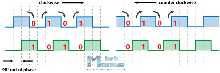
The quadrature encoder works as follows : The A,B pulses of the encoder are phase shifted by 90° or -90° based on the sense of rotation. We sampled the signals at the rising and falling edges and based on the state of other wire we can tell the angle of rotation since there are a fixed no. of pulses that an encoder can generate in 1 rotation known as its ppr(pulse per rotation) value.

- Reset
It is the state achieved when the reset signal is active. It sets the error, previous error, accumulated error, P, I, D to zero. Next state is calculate PID. This state is achieved through synchronous input. The machine starts from this state whenever it starts afresh. - Calculate PID
In this state the value of P, I, D is calculated using the specified values of Kp, Ki, Kd, and the values of error, previous error, accumulated error. Next state is Adjust. - Adjust
In this state the value of sum that is P + I + D is so adjusted so that it does not exceed the limit of the possible values of the output. - Calculate Output
This state produces the output of sign and calculates the duty cycle required further it pushes the value of error to previous error and adds the value of error to the accumulated error. - PWM Output
This state generates the PWM output. It uses the duty cycle calculated in the previous state and sets a counter which counts till Max value minus duty cycle and then changes the signal to high then again count till the duty cycle thus, overall giving the required duty cycle.
Finally we Tune the PID controller by controlling the values of Kp, Kd, Ki.
- Here we have not use Floating points so the resolution is limited to integers.
Motor position control is one of the highest used aspects of a machine. So here we have implemented this on an FPGA taking advantage of the high amount of parallel processing and fast execution of tasks so that the machine has a very less response time and it can react to situations quickly it even has a great amount of accuracy and precision. This in turn makes the machine more reliable and more useful in task where there is high amount of risk involved such as in this sector of healthcare.

- https://en.wikipedia.org/wiki/PID_controller#Mathematical_form
- https://www.researchgate.net/figure/The-structure-of-typical-control-system-With-PID-controller_fig1_304187695
- https://en.wikipedia.org/wiki/Process_variable
- https://en.wikipedia.org/wiki/Rotary_encoder
- https://en.wikipedia.org/wiki/PID
- https://en.wikipedia.org/wiki/Field-programmable_gate_array#:~:text=A%20field%2Dprogrammable%20gate%20array,term%20%22field%2Dprogrammable%22.
- https://www.tutorialspoint.com/digital_circuits/digital_circuits_finite_state_machines.htm
- https://www.omega.co.uk/prodinfo/pid-controllers.html
- https://www.intechopen.com/books/advances-in-pid-control/pid-controller-using-fpga-technology