For the first milestone, you will be building "Addressable" RGB LEDs which can be connected in series with one another and can have patterns generated from them. You will need to utilize any development board of your choosing to generate a RGB node. By the week of OCTOBER 11, you will be expected to come into lab with a fully operational RGB node ready to be connected together. Your node will be tested individually during that lab period, with your documentation (code and readme) being graded throughout the week.
Your grade will be broken up as follows:
- RGB Node Performance 60%
- Code Documentation 20%
- Readme 20%
In the following scene from Netflix's "Stranger Things", Will Byers stuck in a parallel dimension can only communicate to his mother by causing Christmas Lights to light up. The mother then strings up a set of lights like a Ouija Board so they can communicate back and forth.
For starters, the entire network of devices will look similar to the image below.
Each of these RGB Nodes will be responsible for taking in a string of Hex values over the UART RX Line, using the 3 least significant bytes as their own RGB values. These RGB values then need to be converted and transformed into Duty Cycles to replicate the proper color. Since the incoming string may be at most 80 bytes, the remaining string after removing the 3 least significant bytes needs to be transmitted over the UART TX line to the next node.
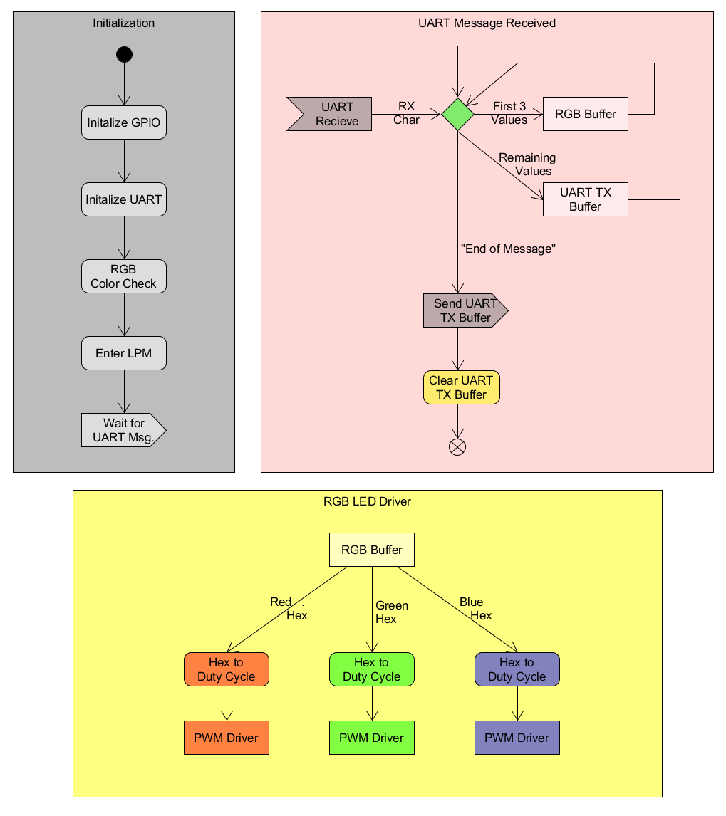
The RGB Node needs to be configured to initialize all timers and peripherals upon starting up and enter a Low Power Mode while waiting for a message over UART. When a message begins to be received over UART, the first 3 bytes should be stored into an RGB buffer which can then be used to set the duty cycles for the RGB LED. The rest of the message should be placed into a UART TX buffer and when the incoming message is complete, should then be sent out over the UART TX Line. Once the message has been transmitted, you should then set your RGB LED accordingly. The flow of this code can be seen below.
To make sure that everyone can talk with one another, we need to ensure that everyones UART settings are the same. For this project, your UART should be set to:
- 9600 BAUD
For starters, we need to establish how each of these node know how many bytes are to be expected for each message. Since each node will be using 3 bytes to set their RGB, we would need at least 3bytes* 26 nodes = 78 bytes. For debugging purposes, we would like to have at least one byte at the end of the message so that our head node can determine whether or not each node removed the first 3 bytes from their received message. This means we will need an additional byte at the end of the message, bringing our total to 79 bytes. It would also be extremely convenient if each node could know how many bytes to expect in a message. For this we can easily add a byte to the beginning of our message to tell each node how many bytes to expect, bringing the total to 80 bytes.
| Byte Number | Contents | Example |
|---|---|---|
| Byte 0 | Number of bytes (N) including this byte | 0x50 (80 bytes) |
| Bytes 1-(N-2) | RGB colors for each node | 0xFF (red) 0x00 (green) 0x88 (blue) ... |
| Byte N-1 | End of Message Character | 0x0D (carriage return) |
The following would be received by your node.
| Byte Number | Content | Meaning |
|---|---|---|
| Byte 0 | 0x08 | 8 total bytes in the package |
| Byte 1 | 0x7E | Red (current node): 50% duty cycle |
| Byte 2 | 0x00 | Green (current node): 0% duty cycle |
| Byte 3 | 0xFF | Blue (current node): 100% duty cycle |
| Byte 4 | 0x40 | Red (next node): 25% duty cycle |
| Byte 5 | 0xFF | Green (next node): 100% duty cycle |
| Byte 6 | 0x00 | Blue (next node): 0% duty cycle |
| Byte 7 | 0x0D | End of Message Check byte |
After taking Bytes 1-3 for use in the current node, the message would be repackaged into a new message and transmitted to the next node.
| Byte Number | Content | Meaning |
|---|---|---|
| Byte 0 | 0x05 | 5 total bytes in the package |
| Byte 1 | 0x40 | Red (current node): 25% duty cycle |
| Byte 2 | 0xFF | Green (current node): 100% duty cycle |
| Byte 3 | 0x00 | Blue (current node): 0% duty cycle |
| Byte 4 | 0x0D | End of Message Check byte |


