Skip to content
New issue

Have a question about this project? Sign up for a free GitHub account to open an issue and contact its maintainers and the community.

By clicking “Sign up for GitHub”, you agree to our terms of service and privacy statement. We’ll occasionally send you account related emails.

Already on GitHub? Sign in to your account

Gen2.1.8 (ex2.10) (I seem to have found a new board) #25

Open
Tommyboi2001 opened this issue Sep 19, 2023 · 198 comments
Open

Gen2.1.8 (ex2.10) (I seem to have found a new board) #25

Tommyboi2001 opened this issue Sep 19, 2023 · 198 comments

Comments

@Tommyboi2001
Copy link

20230919_083325
20230919_083256

@Tommyboi2001
Copy link
Author

first is slave second is master

@RoboDurden RoboDurden changed the title I seem to have found a new board Layout 2.10 : I seem to have found a new board Sep 19, 2023
@RoboDurden
Copy link
Owner

RoboDurden commented Sep 19, 2023

Added it to this repo.
If you plan to use your board, please provide a high-resolution photo of front and back where we can trace some led pins and maybe mosfet and hall pins just by looking on the photo.

Like https://github.com/RoboDurden/Hoverboard-Firmware-Hack-Gen2.x/blob/main/Schematics_2.3/front-back.jpg

@Tommyboi2001
Copy link
Author

board complete

@RoboDurden
Copy link
Owner

Great!
I can not read the complete mcu type. Is it a GD32F130 C6 or C8 ?
C6 does only have 32 kB flash which might very well not be enough for my coming SimpleFOC firmware.
For this Gen2.x firmware it does not make any difference between a 32 kB and a 64kb MCU.

@Tommyboi2001
Copy link
Author

I'm pretty sure its c8, but I will confirm when I get home.

@Tommyboi2001
Copy link
Author

It is GD32F130 c8

@Tommyboi2001
Copy link
Author

board complete with trace
Did Some pin tracing

@RoboDurden
Copy link
Owner

Your CLK pin is wrong:

grafik

Try to trace some led pins - good for debugging like config.h:

#define TEST_HALL2LED // led the 3-led panel blink according to the hall sensors

Cheap CC dcdc converters for a 10s liion battery : "LM2596 60V"

https://www.aliexpress.com/item/1005004225291490.html

Or a 12 or 24V battery or some notebook power supply that outputs somewhere from 14V to 21V.
Then buy
https://www.aliexpress.com/item/1005006015237499.html
or
https://www.aliexpress.com/item/1005006000681109.html

Unfortunately i do not find 12 day shipping offers for these items on Aliexpress.

Or you watch my latest youtube videos and buy https://www.aliexpress.com/item/1005004966830126.html

https://youtu.be/KYcyNHunJU8

bye.

@Tommyboi2001
Copy link
Author

Sorry for the confusing labels, I did know that that was the clock pin. The green yellow and blue traces are the mosfet control

@RoboDurden
Copy link
Owner

have modfied your pin tracins and added it to the Schematics_2.10 folder.
Your 6 mosfet pins seem to be compatible. So if you had a 2A CC power supply, you could already test the motor.
I do not see little smd transistors for the led pins! Are they on the led panles ?
Adding some led output will make it easier and more safe to test the firmware !!

grafik

@pacraf
Copy link

pacraf commented Oct 28, 2023

So by chance I landed with this layout too.
missing info in screen below
image

@RoboDurden
Copy link
Owner

RoboDurden commented Oct 28, 2023

Great.
B6 and B7 will be USART0 and can be used for remote uarst control.
But where is the usual Master-Slave connector on this layout ?

And mostly, you have a led module with 2 led like the one you traced, and a module with 3 led. So i guess that PA12 would control the orange led on that other led-module.

I will make a defines-2_10.h ready for you tomorrow. Here in germany it now is 21:04 and i will go to bed soon.
You should please install Keil and F7+F8 yourself.
It will need many compilations until all pins work properly. I can not do this for you all the time.

@RoboDurden
Copy link
Owner

@Tommyboi2001 , what happened to you ??

@RoboDurden
Copy link
Owner

I see that the little led transistors are on the led module, not the mainboard. Then these pins could probably also be used for serial communication..

@pacraf
Copy link

pacraf commented Oct 28, 2023

I will reverse it all soon. slave board too, comnnection, too.
If you could please make as good as you think it should work, then I will try also Keil. I hate Keil. It was long time ago when I had to write for '51 in Keil at school. It was not my story definetely. Maybe it is time to say hello again... anyway, I am not good at programming. rather copy from internet some good, well described stuff and slighly modify by myself... that's me...

@pacraf
Copy link

pacraf commented Oct 28, 2023

And some slave details
image

@pacraf
Copy link

pacraf commented Oct 28, 2023

Tommorow or next day I will prepare safe power supply and install keil.
Anyway it would be great if you could preapre file as far as you can, to limit mistakes area...
is there anything I can add to board information?

@RoboDurden
Copy link
Owner

Onoff button and hold pin will be important.
But they are tricky to trace.

So try and error might be faster..

@pacraf
Copy link

pacraf commented Oct 29, 2023

I think it is like below pic. Is it sharing same layout like any 2.x? or it's different completely?
I mean if there would be 90%the same, then I would check again these 10% different, to be sure they are not mixed up, but really different...

image

@RoboDurden
Copy link
Owner

Okay i have added the config_2-10.h and also compiled some test binaries: https://github.com/RoboDurden/Hoverboard-Firmware-Hack-Gen2.x/tree/main/HoverBoardGigaDevice/BinariesToTest

The config.h is still set to the 2.10 layout.

As the colors of the hall cable are all balck, the ordering could be reverse :-/
So only test with a 2A cc power supply / step down regulator !!
I have set the number battery cells to 6 so the software will not shutoff when the boards are run at 26 Volt.
If you go below 26V, the onoff button might no longer work.

Still missing is the buzzer pin. I guess it is the little transistor right to it:
grafik

I have defined the led colors according to the slave led module with its 3 leds. Looks like the 2 color led panel of the master has different pins for red and green. I guess you can plugin the 3 led panel into the master as well.

All test binaries are compiled with the TEST_HALL2LED define so the three led should rotate when the motor spins with always two led overlapping.

There are 5 mcu pins that are still free and can do analog input:

// 2.10 available for analog input: A4 A6 A7 B0 B1

So i have kept the 2.0 defines:

// ADC defines
#define VBATT_PIN	GPIO_PIN_4	// robo just guessing
#define VBATT_PORT GPIOA
#define VBATT_CHANNEL ADC_CHANNEL_4
#define CURRENT_DC_PIN	GPIO_PIN_6	// robo just guessing
#define CURRENT_DC_PORT GPIOA
#define CURRENT_DC_CHANNEL ADC_CHANNEL_6

Check the log data when you run a uart binary. the battery voltage should vary when you increase/decrease the cc power supply. Current should increase when you put a hand on the motor.

There are two dual opamp chips on board:

grafik

The left one probably is for two lowside gate currents of the two left phases. They will be important for the SimpleFOC firmware.
The other (right) dual opamp should contain the currentDC and maybe the third phase lowside current.

Have fun.

@pacraf
Copy link

pacraf commented Oct 29, 2023

Great!
regarding buzzer, is it possible that base of this transistor of buzzer is pinned to pin 5 uC ? it is called PF0_OSC_IN
image

@RoboDurden
Copy link
Owner

PF0 could be the buzzer.
have updated and uploaded hoverboard 2.10 master Uart.bin

P.S as i have said, i do not really like to compile binaries when you do not test them yet anyway.

@pacraf
Copy link

pacraf commented Oct 29, 2023

So the current status is that:
-master board is unlocked, loaded with precompiled bin file.
-powered securely with cc limit

  • after loading board makes start sound.
  • led panel reflects rotation (by hand) of motor with overlaping leds.
  • board not holding power. have to lock it with shortcable.
  • no communication to lolin (loaded TestSpeed.ino as it is , except:
#define _DEBUG      // debug output to first hardware serial port
#define DEBUG_RX    // additional hoverboard-rx debug output
//#define REMOTE_UARTBUS

I can not see any communication, so I suppose uC will not rorate motor until receives frame witg requested speed etc..

Any suggestion (chaged rx with tx done... )?

I will look if I did not any mistake (again)

@RoboDurden
Copy link
Owner

first try the master_dummy to verify that the 6 bldc mosfet outputs and the 3 three hall inputs are correct.
I assume you directly flashed hoverboard 2.10 master Uart.bin. Then without communication, motors will not spin and you can test the hall sensors via manually spinning the motor. But the ordering might still be wrong. So the dummy should be tested first.

remote serial should be connected to


	#define USART0_TX_PIN	GPIO_PIN_6	// thanks to pacraf
	#define USART0_TX_PORT	GPIOB
	#define USART0_RX_PIN	GPIO_PIN_7
	#define USART0_RX_PORT	GPIOB
	
	//#define USART0_MASTERSLAVE		// uncomment if this usart is used for master-slave communication
	#define USART0_REMOTE						// uncomment if this usart is used for optional remote control

If you have a pocket DSO, you can look if PB6 is sending some data. (And if ESP32 pin 37 is sending data.)

If board is not holding power then your pin tracing is wrong:

// Self hold defines
#define SELF_HOLD_PIN GPIO_PIN_12		// thanks to pacraf
#define SELF_HOLD_PORT GPIOB

@pacraf
Copy link

pacraf commented Oct 29, 2023

for the time being loaded hoverboard 2.10 master Dummy.bin and basically the same status. (except no sound, but you added buzzer to UART file, so it is ok)
hand rotated wheel = led rotation
motor no sign of life (no noise, no vibration, no significant current draw (60mA) )
for today I have to finish. tomorrow after work will investigate it further.
I assume that even if there would be mixed hall signals, there would be some vibration, chopping movement, whatever.
there must be more wrong, right?
I will also make more reverse on button area, but I am pretty sure I located as on pictures... anyway mistakes happen...
Also will check output with not DSO (don't have, but somewhere I have logic analyzer, have to find it)

@RoboDurden
Copy link
Owner

RoboDurden commented Oct 29, 2023

Yes, with only wrong hall pins or hall order, the motor would stutter or be stuck after a little jump and some current being drawn.

If you had Keil installed, you could compile a 2.0_master_dummy, verify it to work and than only change #define LAYOUT 0 to #define LAYOUT 10

I habe uploaded a hoverboard 2.10 single Dummy.bin now, the buzzer should also work for SINGLE binaries.
Maybe the master_dummy combination does not work. Remember that currently i do not have a test setup here in my train staition.
I could built another 2.0 but have more urgent things on my todo list.

@pacraf
Copy link

pacraf commented Oct 30, 2023

I had some time and looked on some details, and in fact there are small test points called like on picture below, so it has to be accurate. (current measure pins as well are marked on board) . there is also BRK signal,whatever it can be (breaking?). Need to look on that more in details too?

later will look on "power on" circuitry. why it do not want to hold power.

image

@pacraf
Copy link

pacraf commented Oct 30, 2023

Additionally there is no "switch on" circuitry on slave.
Seems that it receives +12V via this quite fat "master slave 3 pin cable" and this is how slave logic is powered.
but will look on this too after we sort out master...

@RoboDurden
Copy link
Owner

yes it is quite common that the slave board does not have a dcdc step down unit but gets the 12V via the mastersalve cable.
and thanks for the i_u, i_v, i_w pins. All of them are available adc pins, so this is the low-side phase current - not neccessary for this old 2.x firmware but needed for the coming SimpleFOC firmware.

the 6 mosfet pins are very restricted by hardware. That is why most layouts have this

#define TIMER_BLDC_CHANNEL_G TIMER_CH_2
#define TIMER_BLDC_GH_PIN GPIO_PIN_10		// all bldc pins same as 2.0, thanks to Tommyboi2001
#define TIMER_BLDC_GH_PORT GPIOA
#define TIMER_BLDC_GL_PIN GPIO_PIN_15
#define TIMER_BLDC_GL_PORT GPIOB
// Channel B
#define TIMER_BLDC_CHANNEL_B TIMER_CH_1
#define TIMER_BLDC_BH_PIN GPIO_PIN_9
#define TIMER_BLDC_BH_PORT GPIOA
#define TIMER_BLDC_BL_PIN GPIO_PIN_14
#define TIMER_BLDC_BL_PORT GPIOB
// Channel Y
#define TIMER_BLDC_CHANNEL_Y TIMER_CH_0
#define TIMER_BLDC_YH_PIN GPIO_PIN_8
#define TIMER_BLDC_YH_PORT GPIOA
#define TIMER_BLDC_YL_PIN GPIO_PIN_13
#define TIMER_BLDC_YL_PORT GPIOB

Try to get the uart working to get some serial log output.

I have uploaded a hoverboard 2.10 single UartBus id0 uart1.bin which should use the 3pin master-slave header for remote control. Maybe you get log output from that tx pin. (and can control via the esp32 tx -> hover.rx)

@RoboDurden
Copy link
Owner

RoboDurden commented Nov 2, 2023

a pocekt dso is a nice thing. Check the delivery time of these offers. If it is 5 days or less then it might be shipping from Poland:

https://www.aliexpress.com/item/1005005644784105.html
https://www.aliexpress.com/item/1005005704582390.html
https://www.aliexpress.com/item/1005005771384739.html

Oh finally a two channel oscilloscope below 40€: https://www.aliexpress.com/item/1005006019697163.html

@pacraf
Copy link

pacraf commented Nov 2, 2023

I will think on that, maybe have something at work in workshop.
but what this can change.
we will OBSERVe the problem, but it seems to be confirmed this will be suppressed line by 2_10. DSO will not change that..
or you are not sure still what is going on? I would rather locate pullups on 2_10 and remove them...

@pacraf
Copy link

pacraf commented Nov 2, 2023

these pullups are physical resistor or internal pullup in GD? will look on that...

@RoboDurden
Copy link
Owner

Yes, it also came to me just now, that you could put a 10k resistor in the tx lines from 2.10.

@pacraf
Copy link

pacraf commented Nov 2, 2023

will try that tommorow. good night !

@RoboDurden
Copy link
Owner

RoboDurden commented Nov 2, 2023

grafik

The idea is like yours: the pullups of 2.10 are to small and therefore the tx line can not be pulled to gnd by the 2.0 boards.
With the resistor, this pullups get weakened. The two resistors should not be too big because then the 2.10 might no longer be able to pull the tx line go gnd (which represents a bit transfered).

one resistor might also work:
grafik

Good night to Poland :-)
You are 1 hour ahead into the night.

@RoboDurden
Copy link
Owner

Better take a 100k potentiometer so you can test a resistance from 1k - 100k :-)

@RoboDurden
Copy link
Owner

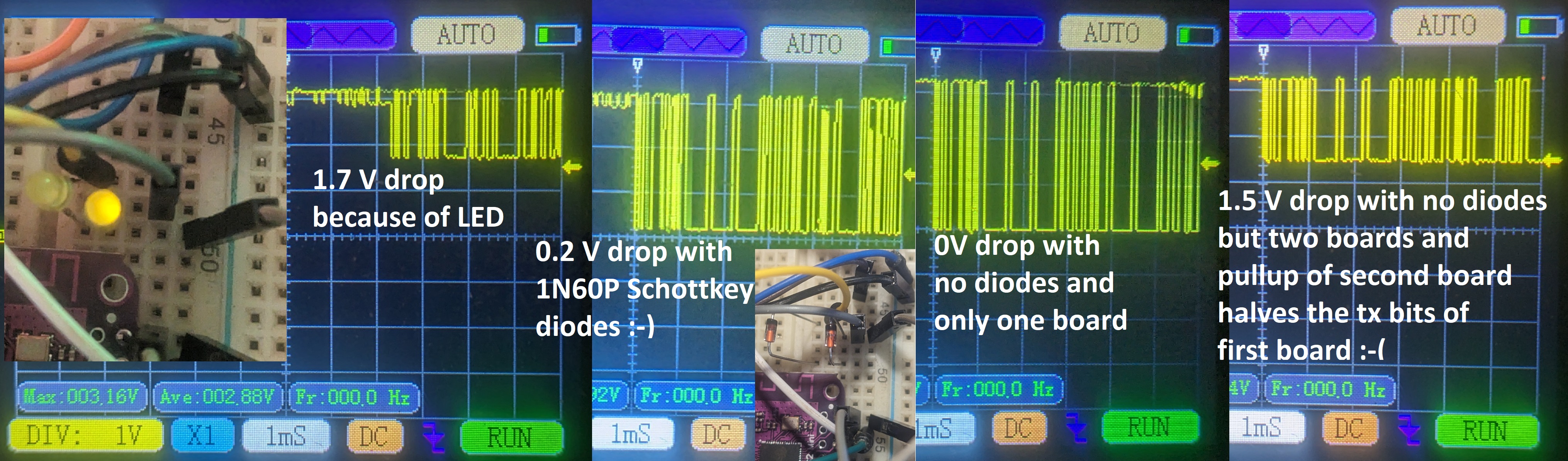
Yes the pullup resistors on the hover.tx lines seem to be the problem.
2.0 has resistors between the mcu and the uart header:
grafik

2.10 may have no resistors in the line but direct connection from mcu to uart header:
grafik

My 2.13 has no restistors in the line for sure:
grafik

The inline resistors of the 2.0 boards from a voltage divider with the many pullup-resistors :-( Therefore the 2.0 tx output can not pull the esp.rx down to gnd anymore :-(

I tried to disable the mcu internal pullup but unfortunately it did have no effect:

void USART0_Init(uint32_t iBaud)
{
#ifdef HAS_USART0
	
	// Init USART0
	#if defined(USART0_REMOTE) && defined(REMOTE_UARTBUS)	// no pullup resistors with multiple boards on the UartBus - Esp32/Arduino (Serial.begin) have to setup pullups
		#define USART0_PUPD	GPIO_PUPD_NONE
	#else
		#define USART0_PUPD	GPIO_PUPD_PULLUP
	#endif
	pinModeAF(USART0_TX, AF_USART0_TX, USART0_PUPD,GPIO_OSPEED_50MHZ);	// // GD32F130: GPIO_AF_0 = USART, GPIO_AF_1 = I2C
	pinModeAF(USART0_RX, AF_USART0_RX, USART0_PUPD,GPIO_OSPEED_50MHZ);	

@pacraf , you can add this change to your setup.c file and see if it helps.
But i did not see a change with my two 2.13 boards.

Two 3mm yellow led did prevent the non sending board to pullup the sending board so badly that ESP32 would not detect the bytes. But the yelllow leds did also add a voltage drop of 1.7V. Still the ESP32 did read the 1.7V as zero and the communication worked with two boards connected (a 3mm green led did not work).

So i replaced the yellow led with little Schottky diodes and these only produced a voltage drop of about 0.2 V :-)

I now think, the UartBus needs Schottky diodes like the 1N60P https://www.aliexpress.com/item/1005004104012198.html

uartbus

@RoboDurden
Copy link
Owner

@pacraf , if you want to build a huge 4wheeler lawn mover i would suggest an ESP32-CAM https://www.aliexpress.com/item/4000844206042.html (Color: CAM-MB With Antenna)
https://lastminuteengineers.com/getting-started-with-esp32-cam/

You could easily (i think) add hoverboard speed/steer levers to
esp32cam

@ncmreynolds
Copy link

ncmreynolds commented Nov 3, 2023 via email

@RoboDurden
Copy link
Owner

I like the Esp32Cam approach because it would already be halfway to an autonomous lawn mover. The cheap camera would only be the intermediate step and to overview the autonomous route..
I do not like rc-remote control at all because it will restrict the project to the usual "stupid fun project"..
The Esp32Cam example arduino code might make it very easy to add remote control via two levers or mouse touches on the smartphone..

@ncmreynolds
Copy link

ncmreynolds commented Nov 3, 2023 via email

@RoboDurden
Copy link
Owner

RoboDurden commented Nov 3, 2023

Okay i have added MASTER control via REMOTE_UARTBUS :-)
@pacraf , now you should be able to only connect two masters (2.0) to the bus and as slaves the other layout (2.10) - the two master-slave cables are not compatible however :-/

4Wheeler.ino:

    SerialServer2HoverMaster oMaster;
    oMaster.iSlave = iSendId;
    switch(iSendId++)
    {
    case 0: // front axis
      oMaster.iSpeed = iSpeed;
      oMaster.iSteer = iSteer;
      break;
    case 1: // rear axis;
      oMaster.iSpeed = iSpeed;
      oMaster.iSteer = iSteer;
      iSendId = 0;
      break;
    }
    oMaster.wState = wState;    // turn on off some led and shutoff master+slave
    oMaster.wStateSlave = wState; // turn on off some led 
    
    HoverSendData(oSerialHover,oMaster);  // hoverboard will answer immediatly on having received this message ...

I also resolved the bugs that slave will not shutoff and REMOTE_UART now running smoothly again.

@pacraf
Copy link

pacraf commented Nov 3, 2023

Hey Robo, it gets complicated as slave 2_10 needs 12V from master. this stays.
only do like below?
image

@RoboDurden
Copy link
Owner

RoboDurden commented Nov 3, 2023

Maybe you find 5V on one of the many 2pin headers of 2.10. Then it would be easier to make the 2.10 the masters and 2.0 the slaves.

But as you already have the 4 ids uartBus setup ready, it would be nice if you would test my latest firmware+4wheeler.ino.
First without any diodes but in hope that my disableing of PULLUP might work for you.
Then with a 100k potentiometer in one 2.10 line (and the other 2.10 not connected).
Finally with at least one diode in a 2.10 line (ant the other 2.10 not connected). Best would be a Schottky diode (the voltage drop gets very small when no current flows (like here with signal transmition only)).

It would be great for me if you finally proove that 4 slaves on my UartBus are possible. With (Schottky) diodes i am very hopeful.
But would be good to learn if some simple resistor could also help.

@pacraf
Copy link

pacraf commented Nov 3, 2023

ok, first with potentiometer. 10k installed like your diagram (so both 2_10 are hanging on this pot10k)
and it is possible to set it up in a way that line is clear for all. but it gets unstable
seems to be a "no go"

time: 725555	HoverSend to: 1
 75 60 C0 00 62 0B 28 00 CC 01 00 00 BC 64 CD AB :-)
time: 725567	rx left: 0	iSlave: 1	iOdom: 402		iSpeed: 0.00		iAmp: 0.00		iVolt: 29.17
time: 726555	HoverSend to: 2
 CD AB :-)
time: 726567	rx left: 0	iSlave: 2	iOdom: 531		iSpeed: 0.00		iAmp: 0.20		iVolt: 29.15
time: 727555	HoverSend to: 3
time: 728555	HoverSend to: 0
time: 729555	HoverSend to: 1
 CD AB :-)
time: 729567	rx left: 0	iSlave: 1	iOdom: 476		iSpeed: 0.00		iAmp: 0.20		iVolt: 29.17
time: 730555	HoverSend to: 2
 CD AFtime: 731555	HoverSend to: 3
time: 732555	HoverSend to: 0
time: 733555	HoverSend to: 1
 02 00 00 61 0B 14 00 BF 01 80 40 0F 51 F3time: 734555	HoverSend to: 2
 75 C0 80 00 65 0B 14 00 7E 01 00 00 88 E3 F3time: 735555	HoverSend to: 3
time: 736555	HoverSend to: 0
time: 737555	HoverSend to: 1
 75 60 C0 80 62 0B 14 00 FF 01 00 00 E6 F7 CD AB :-)
time: 737567	rx left: 0	iSlave: 1	iOdom: 449		iSpeed: 0.00		iAmp: 0.20		iVolt: 29.17
time: 738555	HoverSend to: 2
 CD AB :-)
time: 738567	rx left: 0	iSlave: 2	iOdom: 410		iSpeed: 0.00		iAmp: 0.00		iVolt: 29.14
time: 739555	HoverSend to: 3
time: 740555	HoverSend to: 0
time: 741555	HoverSend to: 1
 F3time: 742555	HoverSend to: 2
 75 C0 80 00 65 0B 14 00 53 01 00 00 40 ED CD 75time: 743555	HoverSend to: 3
time: 744555	HoverSend to: 0
time: 745555	HoverSend to: 1
 60 C0 00 62 0B 80 00 D1 01 00 00 D7 7E CD ABF906 != E29E :-(

@pacraf
Copy link

pacraf commented Nov 3, 2023

as I see it more carefully, it is not as I said. It is not possible to set potentiometer to position where all are talking back.
if it is close to 10k , this 2_0 board can talk back, then you decrease value of pot, and garbage on line appear.
you decrease more, and fimnally 2_10 dominates and talk back.

@pacraf
Copy link

pacraf commented Nov 3, 2023

do you think really shottky will do the job? I have only from shottky family SB560.

@RoboDurden
Copy link
Owner

RoboDurden commented Nov 3, 2023

Yes i am confident that shottky diode will be successfull. SB560 are the bigger ones for 3+ A, so they won't fit into a dupont female cable/protoype board.

It is not possible to set potentiometer to position where all are talking back. if it is close to 10k

Did you indeed mean NOT possible ?

@pacraf
Copy link

pacraf commented Nov 3, 2023

oh yes it did the job.

ime: 661554	HoverSend to: 1
 CD AB :-)
time: 661566	rx left: 0	iSlave: 1	iOdom: 48		iSpeed: 0.00		iAmp: 0.20		iVolt: 29.16
time: 662554	HoverSend to: 2
 CD AB :-)
time: 662566	rx left: 0	iSlave: 2	iOdom: 33		iSpeed: 0.00		iAmp: 0.00		iVolt: 29.15
time: 663554	HoverSend to: 3
 CD AB :-)
time: 663566	rx left: 0	iSlave: 3	iOdom: 35		iSpeed: 0.00		iAmp: 0.36		iVolt: 31.13
time: 664554	HoverSend to: 0
 CD AB :-)
time: 664566	rx left: 0	iSlave: 0	iOdom: 50		iSpeed: 0.00		iAmp: 0.02		iVolt: 35.34
time: 665554	HoverSend to: 1
 CD AB :-)
time: 665566	rx left: 0	iSlave: 1	iOdom: 154		iSpeed: 0.00		iAmp: 0.00		iVolt: 29.16
time: 666554	HoverSend to: 2

@RoboDurden
Copy link
Owner

Awesome :-))

@pacraf
Copy link

pacraf commented Nov 3, 2023

Hell yeah!
here with delay 30 - so almost full comm speed
https://youtu.be/ADhsWMCNjmo

shotky machine here
image

@pacraf
Copy link

pacraf commented Nov 3, 2023

Robo, with pot10k it was NOT possible to find position where all were able to talk back.
if pot value was close to 10k , situation is that 2_10 are not suppressing line, but also they are not able to talk back (only messages from 2_0 visible

if pot is in some mean value (let's say 5k , 50% something like this) - you only see garbage , no 2_0, no 2_10 messages.

you decrease value more , then appears messages from 2_10

so there is NO posistion of potentiometer where all 4 talk back

@pacraf
Copy link

pacraf commented Nov 3, 2023

Robo, Thank you for all your time and effort with this 2_10 case.
As my objectives are to apply these boards (I dont know if I succeed, I do many things and many are never finished, because I give up easy) I will probably come back with some questions topics, but generally I learned a lot.

@RoboDurden
Copy link
Owner

@pacraf : https://youtu.be/NgEQbECmsRk :-)
Currently the video is not public. Please tell me if it is okay for you to share with the Youtube Community :-)

@pacraf
Copy link

pacraf commented Nov 3, 2023

Haha. nice. sure, publish that cable mess. ;)
I still cant believe that until now I did not touched any logic level line to +bat...

@RoboDurden
Copy link
Owner

:-)

@pacraf
Copy link

pacraf commented Nov 5, 2023

Hey Robo, my 4wheeler test rig first drive...
https://youtu.be/X1-D31i7qxM

@RoboDurden RoboDurden changed the title Layout 2.10 : I seem to have found a new board Gen2.1.8 (ex2.10) (I seem to have found a new board) Feb 18, 2024
Sign up for free to join this conversation on GitHub. Already have an account? Sign in to comment
Labels
None yet
Projects
None yet
Development

No branches or pull requests

4 participants