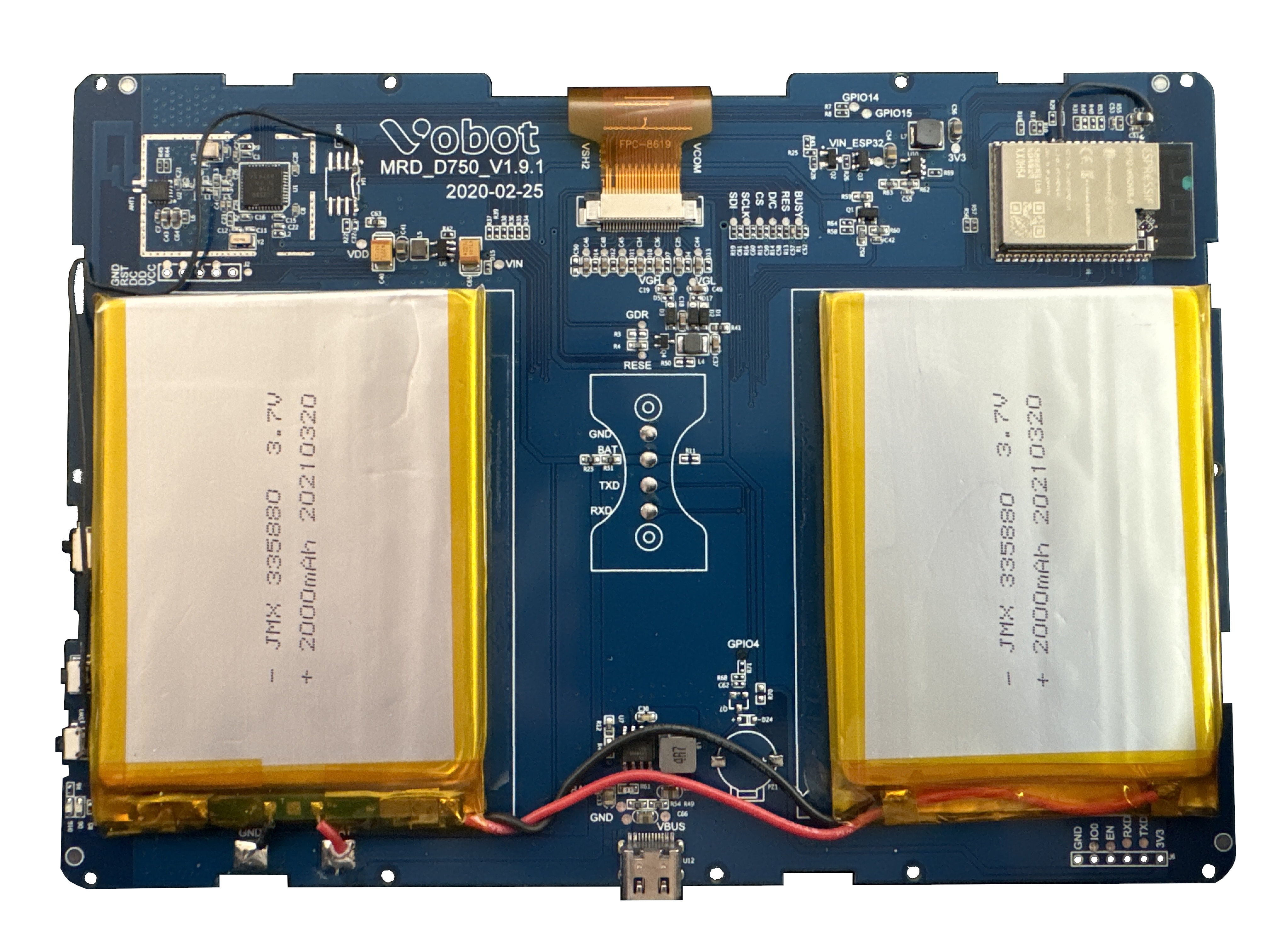
This was tested with a SyncSign model D75C-LEWI-RED. The internal markings indicate the model Vobot MRD_D750, as a result, this model name has been used.
This project would also presumably work with the yellow variant of the device, however, I do not have one to test with. Please open an issue or P/R documenting your test if you happen to get this code working on the yellow display.
The EPD is connected to ESP32 directly via the following pins:
| E-paper label | ESP32 Pin | |
|---|---|---|
| BUSY | <-> | IO25 |
| RES | <-> | IO22 |
| D/C | <-> | IO21 |
| CS | <-> | IO5 |
| SCLK | <-> | IO18 |
| SDI/MISO | <-> | IO23 |
These were determined by checking for continuity between each pin of the ESP32 and the contact pads located on the board.
It appears to be the same (or very similar) display as here and here, the documentation for which can be found here. Tentatively, it appears to be the epd7in5b_V2-demo code, however, a semi-custom driver has been written for consistency with my other projects.
The current driver implementation is only able to update the display once in between resets to the ESP32. Unclear if hardware issue or software error. I have double- and triple-checked the pinouts above, so that does not appear to be an issue.
A possible workaround is to put the ESP32 into a very short deep sleep, though I have had mixed luck with this.
It's worth noting that I have these due to them no longer functioning correctly in production. The issue I'm encountering here may be why I have them.
Has on board a Texas Instruments CC2530 for use with the Zigbee / IEEE 802.15.4 protocol. The chip appears to be paired with a Microchip AT2401C EEPROM which presumably stores some sort of firmware for the CC2530.
There appears to be pins for connecting via SPI south of the CC2530/EEPROM. This would presumably allow for updating and/or modifying the data stored on the EEPROM.
I am admittedly not familiar with this chip or the Zigbee standard, so I haven’t done anything with this. I’m also not very motivated to do anything with it on account of the ESP32's onboard WiFi.
The ESP32 has a programming interface located at the bottom left hand side of the board (when viewed while looking at the display). This interface corresponds to the pins required for programming the ESP32 via serial. I’ve had luck using an Arduino Uno as a programmer.
The onboard WiFi has been tested and is known to work.
The switch labeled SW1 appears to be wired to the ESP32's reset pin. It also appears to do something with the CC2530.