-
Notifications
You must be signed in to change notification settings - Fork 0
Assignment1
For this assignment you will need to write some C++ code to create some 3D objects, including objects of classes that you yourself create, using the T3D rendering framework. The 3D objects and classes that you create in this assignment may be used in your second assignment.
Note on Assignment 2
For assignment 2, you will be creating a short animated movie using T3D. You will choose what the topic of your movie will be (with some restrictions).
While the emphasis of this assignment is on object creation, the emphasis of the next assignment will be on animation. It will be helpful if you start thinking about the topic of your next assignment now, so that you can plan to use objects that you have constructed as part of this assignment. However, if you change your mind, you do not have to use objects from assignment 1 in assignment 2.
This assignment consists of five tasks. All students must complete tasks 1, 2 and 3; all students will also complete either task 4 or task 5. Task 4 is intended for students who are more technically minded, while task 5 is more creative. There will be a similar structure for assignment 2.
This task is to create a custom object using the Sweep class. The requirements for this object are as follows:
- The sweep profile must contain at least 8 points.
- The sweep path must contain at least 8 transforms.
- Using the makeCirclePath function is not allowed for this object (although you could use another similar function that you create).
- The object should be recognisable so that the accuracy (given the level of detail above) can be verified.
For this task you must create a composite object that is designed to be animated. It does not need to be animated for this assignment, but the hierarchy of sub-objects that you establish should be arranged in a sensible way for later animation.
The requirements are:
- The composite object should be suitable for jointed animation.
- e.g. robot, person, dog, machinery, vehicles.
- The composite object should consist of at least six sub-objects.
- This does not include empty transforms used for joint positioning.
- Sub-objects can use any of the Mesh classes provided in T3D, plus any objects you create.
- This includes the sweep from Task 1 or the custom shape from Task 3.
- There should be transforms representing each joint of the object.
- Modifying the orientation or position of a joint should affect only the appropriate sub-objects.
- e.g. for a humanoid object, rotating the transform for the shoulder, should effect the upper and lower arm and hand.
- The object should be recognisable so that the accuracy (given the level of detail above) can be verified.
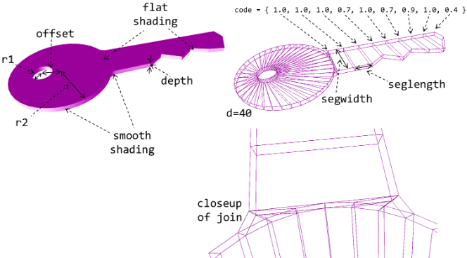
For this task you will create a customisable ‘hole-in-the-wall’ Mesh. The wall may be any size, and the circular hole, may have any radius, position and density (but it will always be oriented along the z-axis, and always be completely within the bounds of the wall).
The constructor prototype will be:
Key(
    int d,              // The density of the key head (outer and inner cylinder)
    float r1,           // The radius of the hole in the key head
    float r2,           // The outer radius of the key head (r1 < r2)
    float offset,       // The displacement of the hole in the key head
    float depth,        // The (uniform) thickness of the key
    float seglength,    // The length of each segment of the key stem
    float segwidth,     // The (maximum) width of the key stem
    vector<float> code  // The width % for each segment of the key
    );
The following diagrams illustrate these parameters and the required arrangement of polygons and face shading. It is not possible to show all vertices diagrammatically, but you should be aware that some vertices will need to be duplicated to achieve the required shading.

The requirements for this task are:
- The object must have correctly positioned vertices.
- The object must have the correctly assembled faces.
- There should be no hidden (or partially hidden) faces.
- There should be no gaps in the mesh surface.
- Faces should be smoothly shaded around the curves and join, but flat elsewhere (this will require duplicate vertices).
For this task you will modify the key to produce something a little more fancy.
The constructor should be:
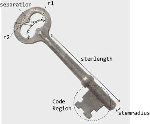
FancyKey(
    int d,              // The density of the key head (outer and inner cylinder)
    float r1,           // The radius of the holes in the key head
    float r2,           // The outer radius of the key head (r1 < r2)
    float offset,       // The separation of the holes in the key head
    float depth,        // The (uniform) thickness of the key
    float stemlength,   // The length of the key stem
    float stemradius,   // The radius of the key stem
    vector<float> code  // An encoding of the key shape
    );
You will be given some latitude to interpret these parameters and may add additional parameters if necessary, but the following diagram should be used as a guide. Although the key head is not quite circular in this diagram, you may make it circular in your mesh if you wish.
The key stem should be a cylinder – careful attention should be given to the join between the key head and the key stem. The code region shown in the diagram would be difficult to implement due to the concave shape, so you may simplify the code region in a similar way to Task 3.

The requirements for this task are:
- The object must have correctly positioned vertices.
- The object must have the correctly assembled faces.
- There should be no hidden (or partially hidden) faces.
- There should be no gaps in the mesh surface.
- Faces should be smoothly shaded around the curves indicated, but flat elsewhere (this will require duplicate vertices).
For this task you need to construct another composite suitable for animation.
The requirements for this composite are as follows:
- The composite object should be suitable for jointed animation.
- e.g. robot, person, dog, machinery, vehicles.
- The composite must have at least six joints.
- The composite should have at least 10 sub-meshes.
- At least one of the sub-meshes should be a new object.
- It is expected that this will be a new sweep (or revolve), but may be a custom mesh.
- There should be transforms representing each joint of the object.
- Modifying the orientation or position of a joint should affect only the appropriate sub-objects.
- e.g. for a humanoid object, rotating the transform for the shoulder, should effect the upper and lower arm and hand.
- The object should be recognisable so that the accuracy can be verified.
- This will be assessed at a higher standard than for tasks 1 and 2.
- It should be a faithful reproduction of a verifiable object at a suitable level of detail.
- e.g. sweeps may need more than 8 points in the profile and/or more than 8 transforms in the path.
To test your code, you should create a new application called Assignment1Test that is a subclass of WinGLApplication.
The init method should create:
- A single directional light.
GameObject *lightObj = new GameObject(this); Light *light = new Light(Light::DIRECTIONAL); light->setAmbient(1, 1, 1); light->setDiffuse(1, 1, 1); light->setSpecular(1, 1, 1); lightObj->setLight(light); lightObj->getTransform()-> setLocalRotation(Vector3(-45 * Math::DEG2RAD, 70 * Math::DEG2RAD, 0)); lightObj->getTransform()->setParent(root); - A camera.
GameObject *camObj = new GameObject(this);
renderer->camera =
    new Camera(Camera::PERSPECTIVE, 0.1, 500.0, 45.0, 1.6);
camObj->getTransform()->setLocalPosition(Vector3(0, 0, 20));
camObj->getTransform()->setLocalRotation(Vector3(0, 0, 0));
camObj->setCamera(renderer->camera);
camObj->getTransform()->setParent(root);
camObj->addComponent(new KeyboardController());
In addition, add one of each object you want to be marked with appropriate separation between objects. It may also be useful to use different material colours for the objects to make it easier to distinguish between them.
For example:
Material *green = renderer->createMaterial(Renderer::PR_OPAQUE);
green->setDiffuse(0, 1, 0, 1);

GameObject* key = new GameObject(this);
vector<float> code = { 1.0, 1.0, 1.0, 0.7, 1.0, 0.7, 0.9, 1.0, 0.4 };
key->setMesh(new Key(40, 1, 5, 2, 0.5, 2, 4, code));
key->setMaterial(green);
key->getTransform()->setParent(root);
key->getTransform()->setLocalPosition(Vector3(0, 0, 0));
key->getTransform()->name = "Key";
Please follow the submission process below very carefully, it is your responsibility to ensure that the correct files (and only the correct files) are submitted in working order.
The marker will have very limited time to correct any errors. If the project cannot be made to run correctly in a reasonable amount of time, your assignment will not be marked.
- Delete the resources folder.
- This folder should not be used by your project and contains large files that are not needed for this assignment.
- Double check that the project still runs as expected (and that the correct application is instantiated).
- In Visual Studio, select Clean Solution from the build menu.
- This is to avoid uploading object files and to ensure a clean build when the marker runs your program.
- Triple check that the project still runs as expected.
- Choose Clean Solution from the build menu again. Do not run your program again after this stage!
- Quit Visual Studio and zip your assignment folder.
- Submit the zip via MyLO.
- After submitting, unzip your submission to a new location and quadruple check that it works.
You are encouraged to use relevant code from the T3D framework, lectures or tutorials, as the starting point for any new classes that you create, but must clearly acknowledge the origin of such code (in the comments). Similarly, if you find code-snippets or other helpful information online, this also needs to be acknowledged in the comments.
However, this is an individual assignment, which should otherwise be your own individual work. It is expected that you will work with and get (limited) help from other students, but may not use any part of their code or the code of previous students in your solution.
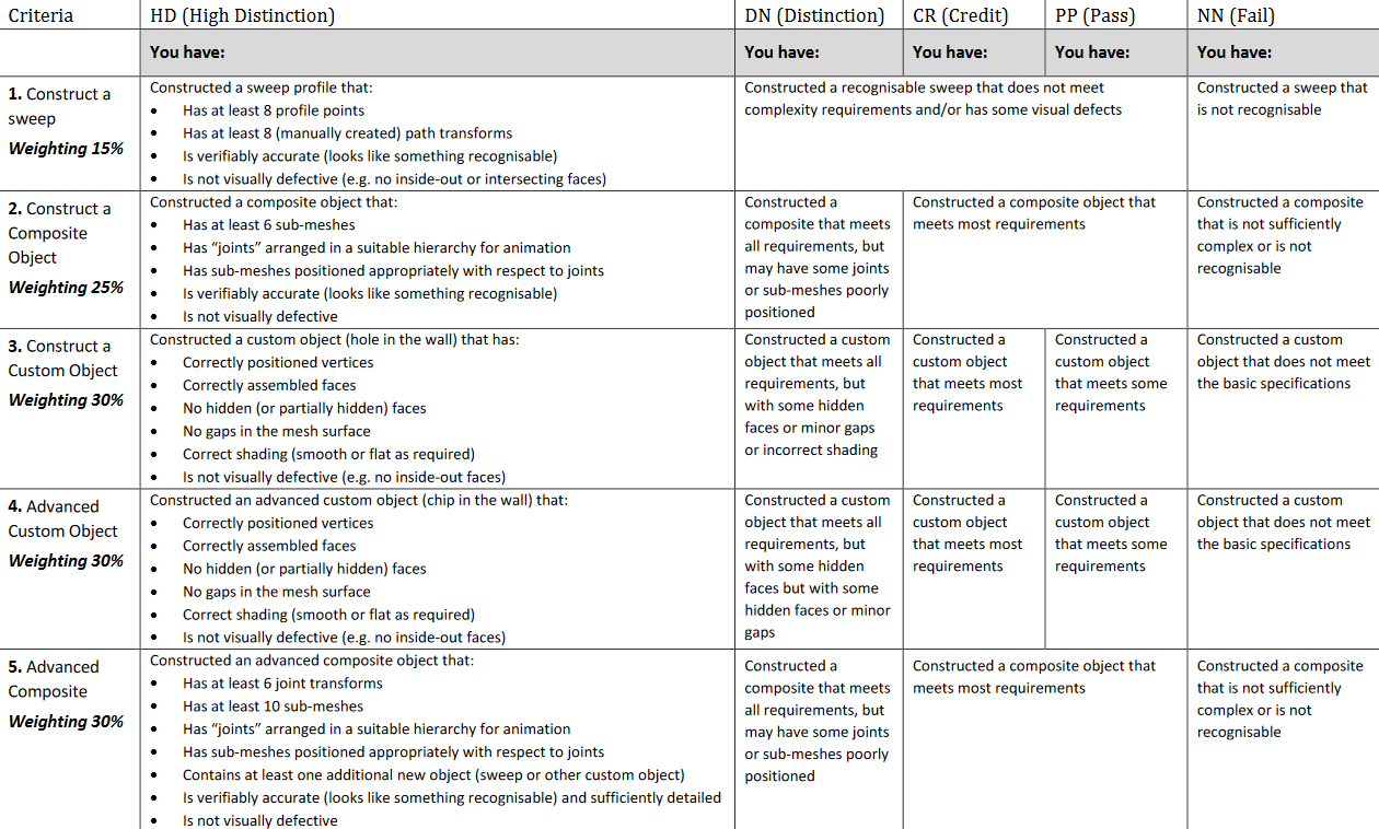
The assignment is worth 15% of the unit mark, and marked out of 100.
All testing of code will be done using Visual Studio on Windows.
Your code will be tested both by running what you submit and by viewing your code. Your code may also be run using separate test code.
| Unit learning outcomes | |
|---|---|
| On successful completion of this unit, you will be able to: | Task criteria |
| 1. Apply programming paradigms for storing and displaying graphical images efficiently | All |
| 2. Manipulate graphics data using mathematics techniques | All |
| 3. Apply lighting and shading techniques to achieve simple effects | - |
