-
Notifications
You must be signed in to change notification settings - Fork 2
Example 01: Analog signal readings

Additional documentation for an example supplied with the KeyDetector library that demonstrates use of a library to get analog signal readings.
In this example we will create sort of absolute rotary encoder using potentiometer and KeyDetector library. Rotation of the knob results in printing its current position and direction of rotation. The whole range of rotation is divided into several segments with the middle points at 25%, 50%, 75% and 100% of the range. Hence the segments: [12.5% .. 37.5%], [37.5% .. 62.5%], [62.5% .. 87.5%], [87.5% .. 100%]. Once the bounds of segments are crossed the output is printed.
ADC (analog-to-digital converter) used in Arduino UNO has resolution of 10-bit, so aforementioned ranges correspond to the following levels of signal read from analog input: [127 .. 383], [383 .. 639], [639 .. 895], [895 .. 1023] (with middle points at 255, 511, 767 and 1023 respectively).

We will use KeyDetector to listen for the signal to fall into one of these ranges and then determine the direction of rotation by comparing current range with the previously detected one.
- Arduino UNO or compatible
- 10kOhm potentiometer
- 1MOhm resistor (optional)
- 100nF capacitor (optional)
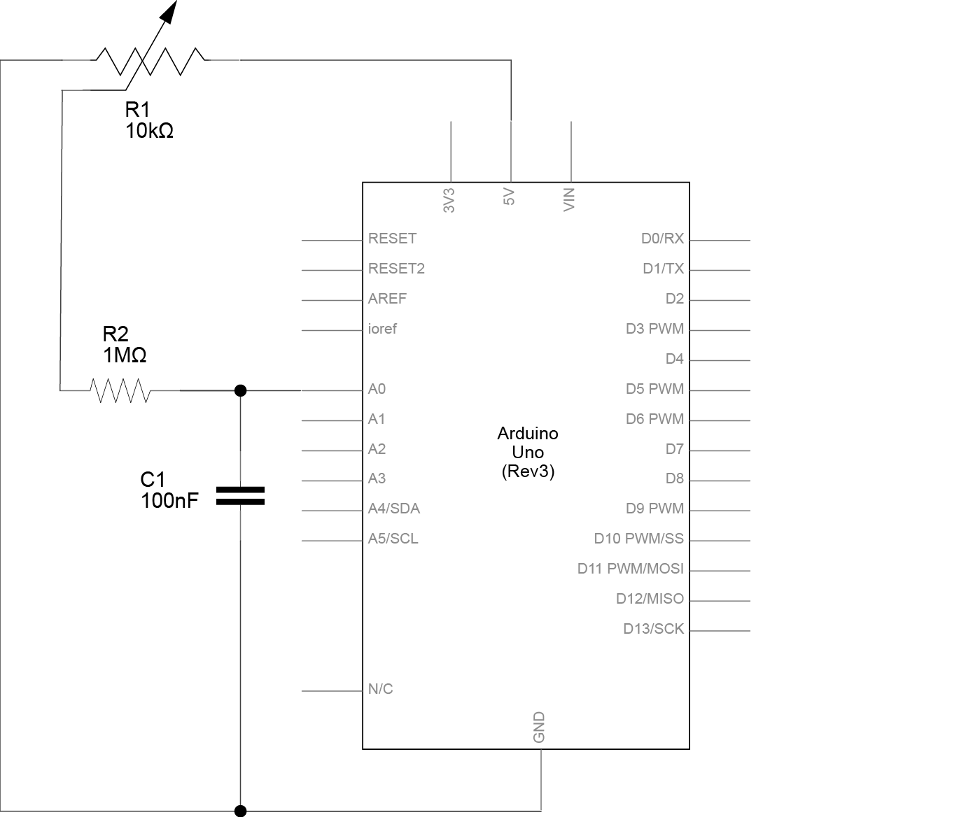
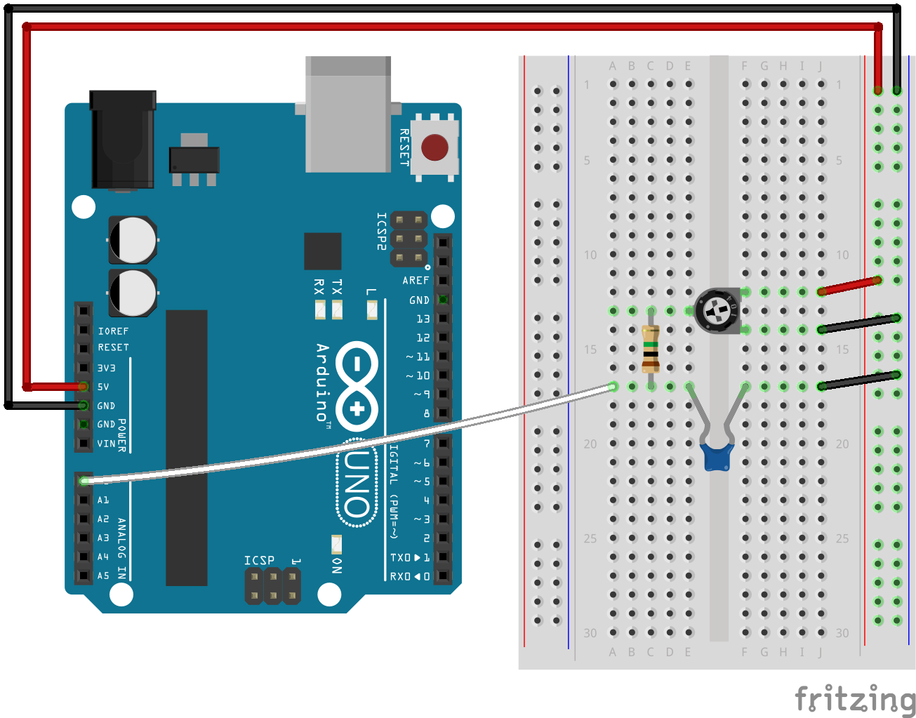
Schematic for this example is very simple. Resistor R2 and capacitor C1 form optional low-pass RC filter. It helps to smoothen any transient processes or ripple that may occur during pot rotation. You may opt not to implement one (or implement version with another R, C values - I just used ones that happened to be in possession at the time).

Connect two side legs of potentiometer: one to 5V and other to ground.
Connect middle leg of potentiometer through 10kOhm resistor to analog input A0. Connect capacitor in parallel with the load (in this case in parallel with A0 input of Arduino): connect anode of capacitor to A0 pin and cathode to ground (if you're using ceramic capacitor you don't have to worry about polarity). Resistor and capacitor form low-pass RC filter. If you'll choose not to implement one, connect middle leg of potentiometer directly to the A0 pin.

Annotated sketch is supplied with the library and can be found at "examples/Example-01_Analog/Example-01_Analog.ino".
Simulation of this example is available on Wokwi. It is possible to interact with the simulation using mouse or keyboard with page up, page down and arrow keys (make sure to focus the potentiometer by clicking on it first).
After compiling and uploading sketch to Arduino, open Serial Monitor and start rotating the knob of potentiometer. Current position of the knob and direction of rotation will be printed every time the signal of potentiometer will cross the bound of each segment of the range.
