ESP8266 Compatible IR Blaster that accepts HTTP commands and emits IR signal through attached IR Led
The purpose of this project was to create a Wi-Fi enabled IR blaster that could be controlled with voice. This was designed with the NodeMCU board but should be compatible with multiple ESP8266 variants
Includes a functional web portal for code capture, output monitoring, and device state tracking
As of the ESP8266 Arduino Core 2.4.0 lwIP vesion 2.0 is default. This causes problems and crashing and it is recommended you use lwIP 1.4. Go to Tools > lwIP Variant > lwIP 1.4 (Prebuilt)
- Install Arduino IDE
- Install ESP8266 Arduino Core
- Install the following libraries from the Arduino IDE Library Manager:
ESP8266WebServerESP8266WiFiArduinoJsonWiFiManagerEasyNTPClientIRremoteESP8266as well asCryptosuitewhich is not on the IDE - Load the
IRController.inoblueprint from this repository - Upload blueprint to your ESP8266 (the .ino file). Monitor via serial at 115200 baud rate
- Device will boot into WiFi access point mode initially with SSID
IRBlaster Configuration, IP address192.168.4.1. Connect to this and configure your access point settings using WiFi Manager. If your router supports mDNS/Bonjour you can now access your device on your local network via the hostname you specified (http://hostname.local:port/), otherwise via its local IP address (this IP address is displayed on the serial output)

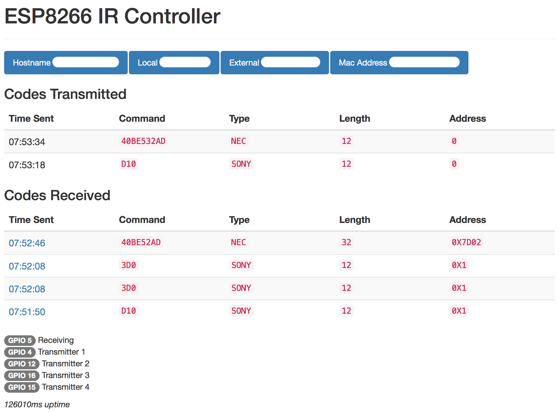
You may access basic device information at http://xxx.xxx.xxx.xxx:port/ (webroot)
Your last scanned code can be accessed via web at http://xxx.xxx.xxx.xxx:port/ or via serial monitoring over USB at 115200 baud. Most codes will be recognized and displayed in the format A90:SONY:12. Make a note of the code displayed in the serial output as you will need it for your maker channel URL. If your code is not recognized scroll down the JSON section of this read me.
For sending simple commands such as a single button press, or a repeating sequence of the same button press, use the logic below. This is unchanged from version 1. Parameters
pass- password required to execute IR command sendingcode- IR code such asA90:SONY:12pulse- (optional) Repeat a signal rapidly. Default1pdelay- (optional) Delay between pulses in milliseconds. Default100repeat- (optional) Number of times to send the signal. Default1. Useful for emulating multiple button presses for functions like large volume adjustments or sleep timerrdelay- (optional) Delay between repeats in milliseconds. Default1000out- (optional) Set which IRsend present to transmit over. Default1. Choose between1-4. Corresponding output pins set in the blueprint. Useful for a single ESP8266 that needs multiple LEDs pointed in different directions to trigger different devices
Example:
http://xxx.xxx.xxx.xxx:port/msg?code=A90:SONY:12&pass=yourpass
For more complicated sequences of buttons, such a multiple button presses or sending RAW IR commands, you may do an HTTP POST with a JSON object that contains an array of commands which the receiver will parse and transmit. Payload must be a JSON array of JSON objects. Password should still be specified as the URL parameter pass.
Parameters
data- IR code data, may be simple HEX code such as"A90"or an array of int values when transmitting a RAW sequencetype- Type of signal transmitted. Example"SONY","RAW","Delay"or"Roomba"(and many others)length- (conditional) Bit length, example12. Parameter does not need to be specified for RAW or Roomba signalspulse- (optional) Repeat a signal rapidly. Default1pdelay- (optional) Delay between pulses in milliseconds. Default100repeat- (optional) Number of times to send the signal. Default1. Useful for emulating multiple button presses for functions like large volume adjustments or sleep timerrdelay- (optional) Delay between repeats in milliseconds. Default1000khz- (conditional) Transmission frequency in kilohertz. Default38. Only required when transmitting RAW signalout- (optional) Set which IRsend present to transmit over. Default1. Choose between1-4. Corresponding output pins set in the blueprint. Useful for a single ESP8266 that needs multiple LEDs pointed in different directions to trigger different devices.
3 Button Sequence Example JSON
[
    {
        "type":"nec",
        "data":"FF827D",
        "length":32,
        "repeat":3,
        "rdelay":800
    },
    {
        "type":"nec",
        "data":"FFA25D",
        "length":32,
        "repeat":3,
        "rdelay":800
    },
    {
        "type":"nec",
        "data":"FF12ED",
        "length":32,
        "rdelay": 1000
    }
]
Raw Example
[
    {
    "type":"raw",
    "data":[2450,600, 1300,600, 700,550, 1300,600, 700,550, 1300,550, 700,550, 700,600, 1300,600, 700,550, 700,550, 700,550, 700],
    "khz":38,
    "pulse":3
    }
]
To send the signal using the IFTTT Maker channel or the IR Controller smart home skill, simply take your JSON payload and remove spaces and line breaks so that entire packet is on a single line, then added it to the URL using the plain argument.
Sample URL using the same 3 button JSON sequence as above
http://xxx.xxx.xxx.xxx:port/json?pass=yourpass&plain=[{"type":"nec","data":"FF827D","length":32,"repeat":3,"rdelay":800},{"type":"nec","data":"FFA25D","length":32,"repeat":3,"rdelay":800},{"type":"nec","data":"FF12ED","length":32,"rdelay":1000}]
If you are setting up your ESP8266 IR Controller to handle multiple devices, for example in a home theater setup, and the IR receivers are in different directions, you may use the out parameter to transmit codes with different LEDs which can be arranged to face different directions. Simply wire additional LEDs to a different GPIO pin on the ESP8266 in a similar fashion to the default transmitting pin and set the corresponding pin to the irsend1-4 objects created at the top of the blueprint. For example if you wired an additional LED to the GPIO0 pin and you wanted to send a signal via that LED instead of the primary, you would modify irsend2 in the blueprint to IRsend irsend2(0) corresponding to the GPIO pin. Then when sending your signal via the url simply add &out=2 and the signal will be sent via irsend2 instead of the primary irsend1.
Default mapping
- irsend1: GPIO4
- irsend2: GPIO5
- irsend3: GPIO12
- irsend4: GPIO13
- irrecv: GPIO14
- config: GPIO10
Set GPIO10 to ground to force a WiFi configuration reset, this will boot the device into WiFi host mode with an SSID of 'IRBlaster Configuration' and IP of 192.168.4.1
By adding the device and state parameters to your URL or JSON object, the device will remember the last sent state of the device.
Example Turn On URL (if TV was already turned on, this command will do nothing):
http://xxx.xxx.xxx.xxx:port/msg?code=A90:SONY:12&pass=yourpass&device=tv&state=1
Example Turn Off URL (if TV was already turned off, this command will do nothing):
http://xxx.xxx.xxx.xxx:port/msg?code=A90:SONY:12&pass=yourpass&device=tv&state=0
For configuring automation services where the HTML output of the device will never be seen by a human, add &simple=1 to the URL to simplify the data sent and speed up the response time
Example:
http://xxx.xxx.xxx.xxx:port/msg?code=A90:SONY:12&pass=yourpass&simple=1