Feature request: adding Obi Socket #1988
Comments
|
could you add images from the pins with description which pin is what? |
|
The descriptions of the pins are printed on the PCB. They are similar to the pin names on any FTDI adapter. |
|
you could try to use the generic module (ex. wemos d1 pre 5.11.0 i think) on the web interface and set up your gpio config.
|

|
Some pics from the opened device can be found here: https://github.com/martin-ger/ESP8266-WiFi-Socket |
|
It works somewhat different than the Sonoff basic: a low pulse on GPIO12 switches the relay on, a low pulse on GPIO5 switches it off. |
|
In my Tasmota there is no "Generic" type so I had to edit the templates... |
|
"Generic" has been added during the last days, replacing Wemos D1 Mini and NodeMCU variants. |
|
@Frickelmaster1 |
|
My first Obi socket works fine, the second doesn't. I flashed the binary with ESPloader to the sockets. The first is OK, the second (with exactly the same firmware) is accessible via web interface, the on-off works (including the blue LED) but the relay isn't switching at all. Maybe Martin can explain how he modified Tasmota to make it work with the Obi sockets?! |
|
I did not use Tasmota but my onw software - works fine. I am not into the Tasmota code and platform.io, but use the esp_open_sdk and my MQTT framework. The control of the relay works as follows:
The two ports are even named "RELAY ON" and "RELAY OFF" on the PCB of the ESP. Also have an Arduino sketch that controls the device: |
|
In the sources I read something about "latch" - should be similar to this issue #58. |
|
Although I can't imagine maybe there are differences between my sockets I'll compare them tonight. Strange... one is working fine, the other one doesn't switch the relay - with identical firmware. I'll try to use a modified EXS relay configuration on the second socket. Thanks, Martin! |
|
I have solved the 'pulse issue' by setting GPIO12 to always 0 (as LED) and works fine.
|

|
Got mine today and can confirm @thxthx0 solution. Thanx |
|
Same here. Confirm @thxthx0. Firmware flash with GND/GPIO0 pin method, update to tasmota 5.12, shown config above. works. THANKS! What a great community! |
|
Tried it yesterday in the evening - works fine with Tasmota 5.12.x and "Generic" device with the settings above. Thanks! So my request to add "Obi socket" to Tasmota's sonoff_template.h is no longer necessary :-) Nice! |
|
How did you manage to access Tasmota on the OBI plug? I'm struggling since yesterday evening. I'm able to flash it, but no wifi, no interface, nothing. |
|
build the firmware yourself, enter wifi credentials in the user_config.h and flash again. dont forget to reset the cfg_holder enter wifi data their is not btn on gpio1 thats why you cannot start the manager with btn press and default is wps mode |
|
I'm doing something wrong. edited my wireless settings, including ip It won't connect to my wireless, no ping, etc. |
|
their is nothing more to add, its an esp like in all other devices. do you got other devices with tasmota which are connected to your wifi? ip on 0.0.0.0 for dhcp. no special chars in wifiname and password. how you want to send a ping without an ip or connection to your router wtf dude... even if it says its flashed 100% it can be not flashed due a defect usb flasher or you used wrong device config in arduino/atom. read the flash guides in the wiki. |
|
My ip was set to a fix IP, this is why I was monitoring the IP with ping. I'm using the correct flashing method, I assume - Generic ESP8266 Module. |
|
I have the latest firmware flashed. As the wlan was preconfigured access was possible. But I'm struggeling with the OBI socket and generic Type. Comparing the screen shot from above with the settings I only get 4 entries in the module configuration: GPIO1/3/4/14. So how do you enable the rest of the fields and enter the settings? |
|
Change it to generic, save. It will restart an you'll have the other options as well. |
|
If someone wants to confgure more sensors: the onboard ESP8266 Module with 1MB is similar to 'WT8266-S1'
|

|
Got mine flashed with tasmota and used the settings suggested by thxthx0, but my relay does not turn on. Only Red & Blue LED's turn on. @Frickelmaster1 : Did you get it working on yours? EDIT: MY BAD!!! Relay only works on wall power, not on 3.3V from USB TTL |
|
I tryed to flash it with esptool. after 2-3 trys i got: 00:00:09 APP: starte neu ets Jan 8 2013,rst cause:4, boot mode:(1,6) wdt reset and nothign happend further, i used 5.12 |
|
@Steakschen PreBuild Image or self compiled? |
|
i flashed 2 times, and booted it 5 minutes, now it works |
|
@arendst After playing around with the socket a bit more yesterday (trying to use the existing latching implementation for module EXS_RELAY which I assume is working and remapping the GPIOs), I am not so sure that the Obi socket really has a latching relay, as it would turn off right away when the pulse was over. Edit: On the other hand, @martin-ger 's coding obviously uses pulses and his pictures show the same hardware :-) |
|
I just opened my socket this is not a latching relais. perhaps they use different models? |
|
That's right, it is not a latching relay. There is a standard 16 amp relay, I couldn't measure any differences in power consumption The relay is driven at about 140mA and 5.4 V |
|
Hi all, @thxthx0, thanks for clarification - should have checked my inbox a bit earlier :-) I just picked up another one at Obi and can confirm that also with stock firmware, across the pins driving the relay coil, there is a constant voltage visible while the output is active. The "Relay On" trace from the ESP8266 board goes into something that looks like a circuit around two transistors (flip flop, eh? good old times). So I guess we don't need any code changes after all. Thanks to all! |
|
Is it normal that the devices get hot? When turned off, it is warm to the touch, but when on it realy heats up. |
|
Yes, seems to be normal (and a 'feature' of this relay ;). Power Consumption of the relay is about 0.75W It also works reliable @ 4V and 0.4W, |
|
Unfortunately the Button1 wired to GPIO14 no longer allows to use the Button usage (usually wired to GPIO0), described on https://github.com/arendst/Sonoff-Tasmota/wiki/Button-Usage Does anybody know how to regain this Button-Usage, e.g. for providing an Access Point with IP address 192.168.4.1? Correction: Button1 works also with GPIO14, I had a problem with the test. |
|
@arendst |
|
This issue has been automatically marked as stale because it has not had recent activity. It will be closed if no further activity occurs. Thank you for your contributions. |
|
Are the tasmota developers against adding a template for the OBI socket and would prefer that one uses the Generic setting? Or would a pull request be appreciated? |
|
Yes, I will also really appreciate to add the adapter configuration to the template ! |
|
Please, Make a PR. Thanks |
|
Created PR #3944 |
|
@renne OBI plug is a cheap china device too... |
|
OBI Socket setting also works for Orvibo S25US https://fccid.io/2ACLPS25US/Internal-Photos/Internal-Photos-2970651 Button, relay and blue LED work. The S25US LED can also be red if the blue is turned off and GPIO12 is on. Though red and blue cannot be on at the same time. I experimented with this using Sonoff 4CH module setting. |
|
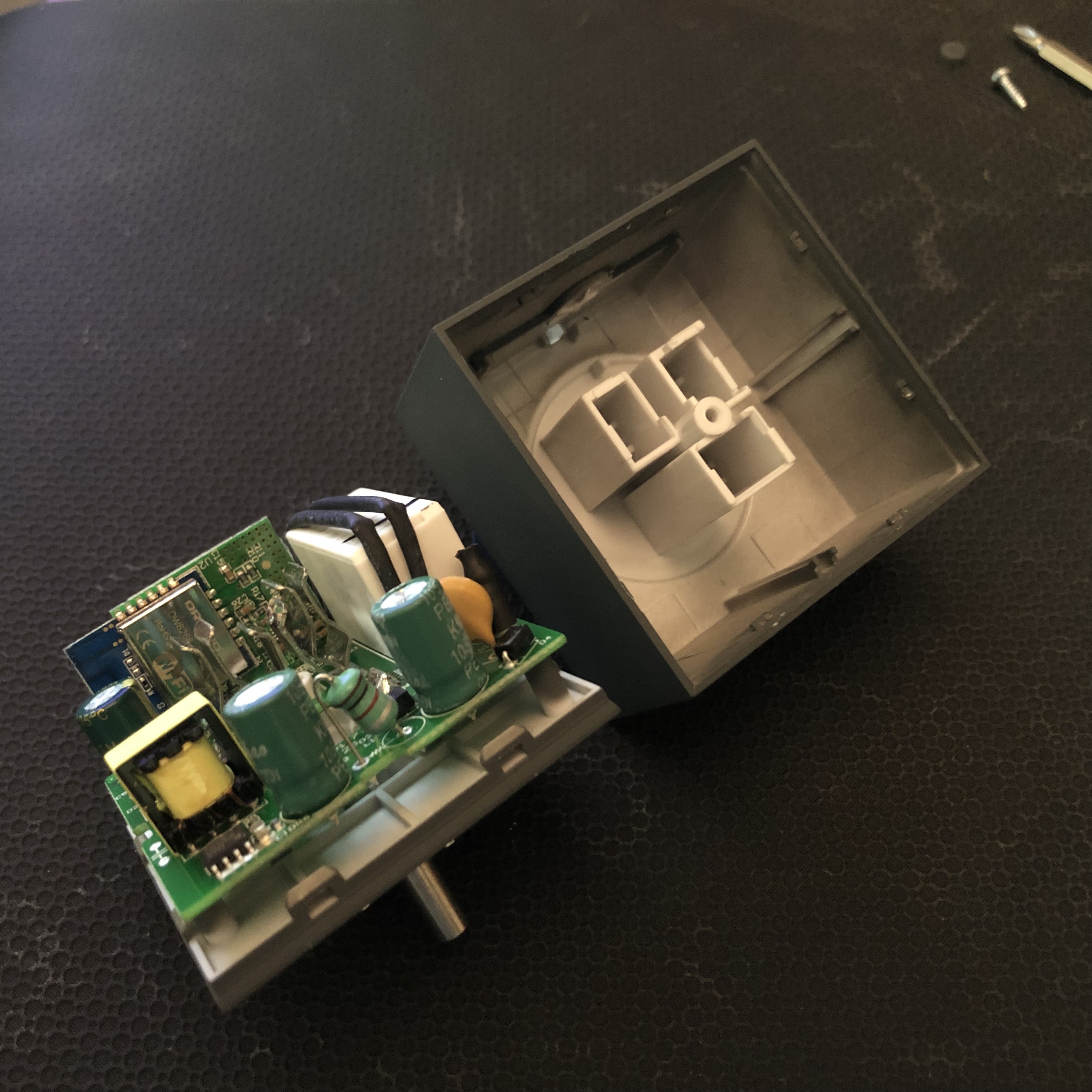
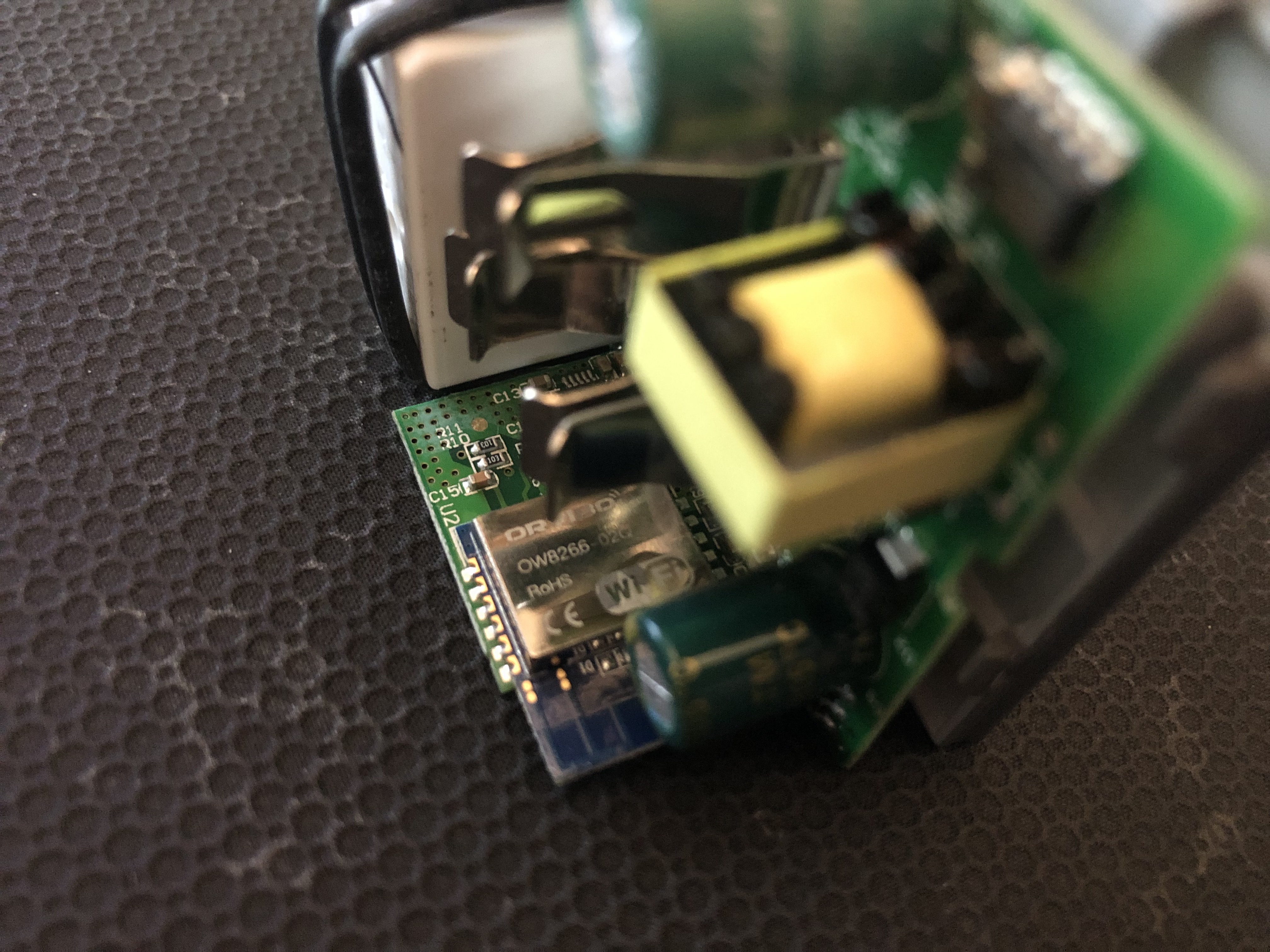
I wonder if this Works for the Orvibo S31 (which has power monitoring) as well. It doesn't have any nice board pins to connect headers to, so it's not as simple as some other devices. I have opened up the outlet and here's what it looks like:
|

|
Interested in the S31 as well. Any try this yet? |
Yeah, I’m just curious if the template is the same before I flash it. |
|
@roger- Did you figure out how to connect to this and flash it? This is the first unit I am trying to flash and I don't see labeled points to connect to. |
|
@KSumwalt no, haven’t tried yet. @mkormendy really? Do you have a link to someone who’s tried it? |
|
A HowTo with USB-Serial converter to flash: |
|
@rudi48 the way you describe is outdated. Devices are supported and easily configured via Template function. See https://blakadder.github.io/templates/ |
|
I've been unable to put in program mode that Orvibo S31 (pictures from @mkormendy above), I don't want to de-solder the board where the 8266 is and accessing the pins is very dificult... |
I spoke too soon, and I've deleted my comment. I got the Smart Life / Tuya apps confused with the HomeMate app which appears to not be Tuya based.
I managed to separate the smaller board from the larger base board with all of the larger components on it. I needed to use a vacuum soldering gun (we have one at work) and that got all of the solder off enough for me to pull the smaller board out. However, I was unsuccessful at my first couple attempts to flash the device with easier access to the pins. I put it down for the past while. I wish they would just allow us to flash our own software on the device, this sort of lock down would obviously void warranties but I wouldn't care at that point. |
German DIY store "OBI" is selling ESP8266-based sockets (very similar to Sonoff S20) for less than 10 EUR.
I got two of these sockets. It's quite easy to flash Tasmota on it but it was neccesary to modify sonoff/sonoff_template.h to make it work correctly. The same reason as with other clones: they assigned the GPIOs randomly to the available functions and chose others than ITEAD with their Sonoffs.
It would be nice if this configuration snippet could be added to the official sonoff_template.h.
I suggest adding these lines to sonoff_template.h for making the Obi Socket work:
{ "Obi Socket", // Obi socket (ESP8266) - https://www.obi.de/hausfunksteuerung/wifi-stecker-schuko/p/2291706
0, // GPIO00 Flash jumper - not available
0, // GPIO01
0, // GPIO02
0, // GPIO03
GPIO_LED1, // GPIO04 LED on top and in switch button
GPIO_REL1, // GPIO05 Relay 1 (0 = Off, 1 = On)
0, 0, 0, 0, 0, 0, // Flash connection
0, // GPIO12
0, // GPIO13
GPIO_KEY1, // GPIO14 switch button
0,
0, // GPIO16
0 //
},
The text was updated successfully, but these errors were encountered: