Battery
The remote (mailbox) module must be autonomously powered. This page discusses powering options for the remote module, and means of reporting the battery state.
Since ESP-01S is used, the only way to report battery voltage is to use an internal ADC connected to the power line (ADC_VCC). ESP-01 data sheets are not very clear on the returned value, but seem to suggest that 1000 is returned per 1 V measured (e.g., 3.3 V would return 3300). Some people in Internet reported this to be the case. I did not observe this on a simple test; so, the first thing was to calibrate the ADC. The graph below shows internal ADC reading as function of power supply voltage:
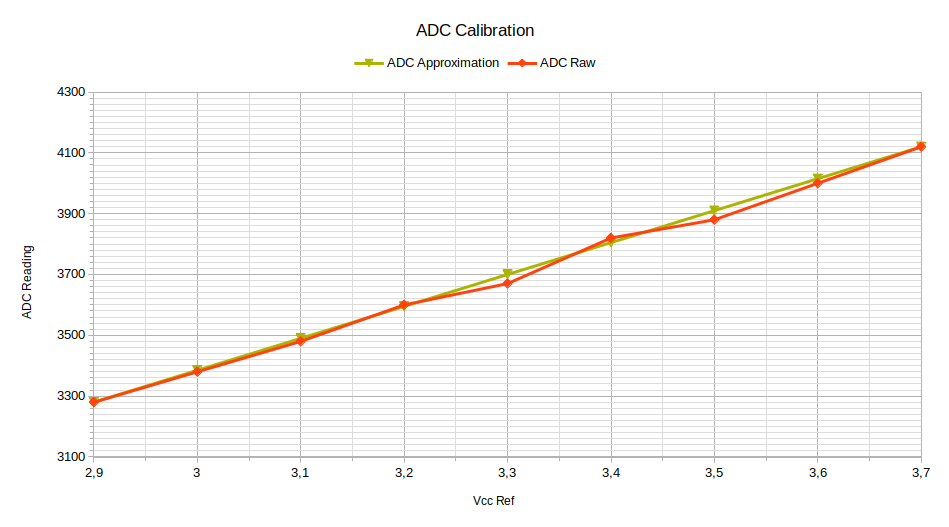
In this test the power was provided by a lab DC regulated power supply (i.e., good steady power source without battery peculiarities). The result shows that the returned values are quite distant from datasheet values. Nevertheless, the curve is confirmed to be linear, which allows using just two coefficients for voltage calculation in program. Conversion to voltage could then be done as follows:
Vadc = A * ADC + B (1)
where:
A = (V[3.7] - V[2.9]) / (ADC[3.7] - ADC[2.9]) =  (3.7 - 2.9) / (4120 - 3280) ≈ 0.000952     (2)
B = V[2.9] - A * ADC[2.9] = 2.9 - 0.000952 * 3280 ≈ -0.223                                  (3)
In practice, in this application it is not required to go to voltage calculation and operate with floating point numbers. The only important takeaway from this exercise is linearity. It is then enough to say that one ADC integer reading (higher) corresponds to battery 100% and another ADC reading (lower) corresponds to battery 0%. What these readings are depends on the actual power source selected, and has to be determined experimentally.
NB: it appears that different circuit boards where ESP sits, or even different ESP chips could exhibit different coefficients, hence per-unit calibration would be desirable (see issue #47).
Another observed issue was reading instability. The same measurement done several times would often yield very different values. To track this, a nearly two-month measurement was undertaken, taking an ADC reading (orange) every day and comparing it with the real voltage (blue) measured with a multimeter:
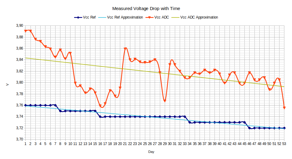
Here the power source was a 18560 rechargeable battery, charged to 75% capacity. Coefficients to calculate the voltage were taken from the previous graph. We can see that the readings are indeed very unstable. There are also some additional effects:
- there is an constant offset of about 0.08 V of measured vs real voltage. Since it accounts for no more than 2% of absolute voltage value, it was not specifically studied further;
- drop rates (angles of the approximation straights on the graph) are not exactly the same for measured and real voltage. It is difficult to see it on the graph, but it can be inferred from calculation. This was not specifically explored either, but is suspected to be attributed to a loss of linearity beyond 3.7 V (area not explored on the first graph).
To counter the measurement instability, software averaging is used. Each newly measured value is averaged with the previous value with a weight of 10%. Thus, several consistent readings are required to move significantly the value. To work across sleep cycles, current value is saved in a specific area of memory ("RTC Memory") surviving deep sleep. Also, to avoid large jumps, readings from off-normal regimes, such as cold start, are discarded. The averaging algorithm can be found in PhysicalMailBox::updateBattery() function.
Remote module power consumption is, essentially, a sum of ESP-01S and HC-12 consumptions. ESP-01S consumes significantly less when its RF module is turned off. HC-12 does not consume much except for the periods when it transmits. These various consumptions were measured and found to be as follows:
| Parameter | Value |
|---|---|
| Cold start (rare) | 85 mA |
| Warm start (main use) | 33 mA |
| HC-12 extra when transmitting | 35 mA |
| Sleep with door open (rare) | 360 µA |
| Sleep with door closed (main use) | 35 µA |
Higher consumption at cold start is expected, since on cold start ESP8266 boots with RF module on, while warm start (wake up from deep sleep) is configured to keep the RF module off.
Assuming an average scenario of two events per day (one delivery from postman and one check from owner), and taking into account that:
- there are two transmissions per event,
- a single transmission in slow FU4 mode takes ~1 s,
- average event duration, from experience, could be generously taken as 10 s, of which 2 s will be transmission,
we can estimate that daily consumption would be:
daily consumption =
    2 events per day * 33 mA warm start consumption
      * (8 s active + 2 s transmitting * 2 with double consumption) / (60 * 60 seconds per hour)
    + 35 µA sleep consumption * 24 hours
    ≈ 1 mAh
which, for a high-capacity 18560 battery with 3400 mAh would amount to ≈ 9 years of service. In practice, it is unlikely to last for that long, because of off-normal events eating up battery, self-discharge currents and impossibility to extract the whole battery capacity with relatively high peak currents.
The first candidate was a 18560 element, potentially coupled with a solar panel if daily consumption would have turned out to be significant (it did not materialize). 18560 has an inconvenience of being quite large (especially when a battery holder is used) and having a full charge voltage of 4.2 V, which is too high for ESP8266 without a voltage converter. I wanted to avoid voltage converters because they complicate schematic. Taking into account very optimistic battery life estimations from the previous section, I decided to look for smaller and less powerful solutions. This is how a 14250 battery came into design. It offers small size (1/2 AA) and nominal voltage of 3.6 V, which can power ESP8266 directly.
Currently, the remote module is powered with one Saft LS14250 battery:

Taking into account the battery nominal voltage 3.6 V and ESP8266 nominal voltage 3.3 V, and looking up the calibration graph, the first naive thought for a reasonable envelope looks like:
| Battery Level | Voltage | ADC Reading |
|---|---|---|
| 100% | 3.6V | 4015 |
| 0% | 3.0V | 3385 |
These constants were recorded in PhysicalMailBox.cpp and submitted to field test.
This setup was deployed in the field, where the battery lasted for three and a half months, behaving as follows:
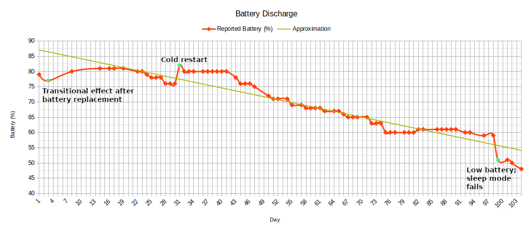
Remarks on the graph:
- apparently, the 3.0 — 3.6 V range is too wide for battery reporting, and more narrow range should be selected;
- cold restart was not linked to battery performance;
- sleep failure occurred earlier than expected.
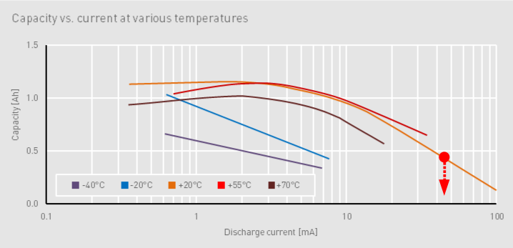
One particularity to consider here is that the reported period was August — November, and in November in my region the ambient (and, hence, mailbox module) temperatures drop to around 0 ℃. It is known that low temperatures could lead to decreased battery capacity. To analyze this point further, we can take a look at Saft's LS14250 datasheet. The datasheet says that consumption peaks of up to 100 mA are tolerated, but seems to suggest that peaks are expected to be in the order of 0.1 s. In our case we have 33 mA steady consumption for a few seconds, plus a couple more seconds with consumption approaching 70 mA. It means that we should rather look for quasi steady-state consumption; let's stick to 35 mA as a reference. If we look at the current-voltage graph of LS14250, we can observe that in these conditions battery voltage could drop well below 3 V, which could lead to instability:
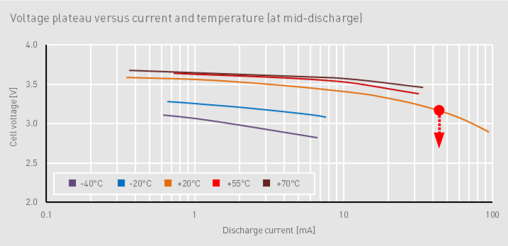
If we turn to the battery capacity, here again, at warm temperatures with high consumption it could be already far less than the declared 1200 mAh. If we go to lower temperatures, it could drop well below 500 mAh:
To test dependency on temperature I undertook another run with a fresh battery taking temperature readouts every day at noon (typical time when a postman passes). To combat premature sleep failures I doubled value of the capacitor backing up the battery and also of the capacitor on the HC-12 wakeup line (C3 and C1 on schematic). Inspite of particularly cold winter, the modified module ran for eight months, as follows:

Green dots indicate module cold restarts due to external factors (not linked to a battery). From this graph we can observe that there is some correlation with the ambient temperature indeed, but not as strong as I was expecting. Summer season starting from day 150 clearly has positive effect on battery readings. Overall, we can conclude that, in spite of pessimistic data sheet graphs, LS14250 battery is usable in mild winters as well.
In order to fix the problem with the reported range, the range in subsequent versions of software was shrank as follows:
| Old ADC Reading | Old % | New % | New ADC Reading |
|---|---|---|---|
| 4015 | 100 | — | — |
| 3927 | 86 (highest observed) | 100 | 3925 |
| 3687 | 48 (beginning of instability) | 20 (low battery threshold) | 3685 |
| 3624 | 38 (lowest observed) | 0 | 3625 |
| 3417 | 5 (low battery threshold) | — | — |
| 3385 | 0 | — | — |
Following observations, the "low battery" threshold was raised from 5% to 20%.
Remote module schematic is inherently battery-unstable. What it means is that the circuit sleeps and consumes low power only if power itself is correctly provided. As soon as a power glitch happens, ESP-01S or HC-12 would not go to sleep correctly, hence, consume more power, and, ultimately, drain battery until the whole circuit fails. ESP has some protection from this, as it sends itself into sleep after 30 s, but there is nothing comparable done for HC-12. The only option here would be to use a transistor to power off HC-12 when ESP-12 goes to sleep — an option I consider somewhat barbaric.
To note that before this failure happens, apparently, there is a period where both ESP-01S and HC-12 sleep correctly but the RF power emitted is reduced to the point where transmission is no longer detected. This, of course, depends on how far your transmitter is and, normally, is only noticeable with significant distance. The reason the "low battery" threshold is set to somewhat high 20% is mostly to cover this period as well.