Soldering and assembling
Following tools are necessary to assemble the light controller PCB:
- Soldering iron with tiny tip (or SMD rework station)
- Solder
- Solder flux
- Couple of tweezers
- Bench magnifying glass or microscope
- Nipper or cutting tool
During soldering try to solder small SMD components first. During the prototype construction, I solder SMD ICs first. After soldering ICs start with other SMD components such as resistors, capacitors, transistors, diodes, and crystals.
After soldering SMD components, install the remaining component in the following order:
- Y2 - 32.768kHz crystal
- R19 - 2.2Ω resistor
- SW1, SW2, SW3 - tactile push switches
- J1 - 2×3 pin header
- J2 - 2 way screw terminal
- BT1 - CR2025 / CR2032 battery holder
- J3 - DC barrel jack base
- U4 - Seven segment display
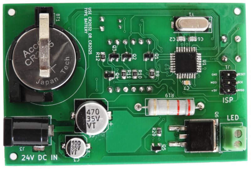
After assembling board may look similar to the images in below:

Instead of using a built-in 7W LED driver, if you plan to use this controller with any other drive mechanism or circuitry then follow the below-mentioned steps:
- Cut-open JP1 jumper located at the top layer of the PCB.
- Connect driver circuit to the Pin1 of JP1 jumper (this is the pin which connected to the PB3 terminal of ATmega8 MCU).

As mentioned above if you plan to use this controller with an external drive circuitry then you don't need to solder following components into the PCB:
- R19, R20
- Q5, Q6
- J2
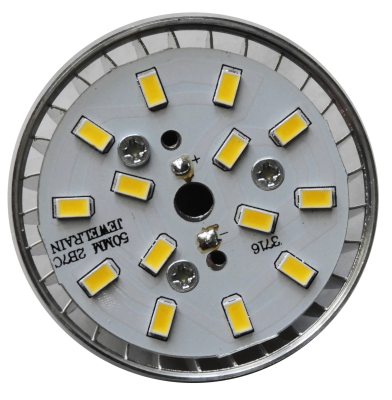
Before soldering 7W LED module, fix it to the given heatsink. To provide sufficient thermal transfer make sure to apply thermal grease between the LED module and heatsink.
While LED lighting for long hours its temperature increase up to 70°C - 80°C. Because of this, make sure to take necessary action(s) to isolate J2 to the LED wire line with temperature. To overcome this, in prototype build I drive this wire through a high-temperature resistant Basalt sleeve.