Digital piano firmware for the Raspberry Pi Pico. This project only attempts to expose the keyboard as a MIDI device. The purpose is to revive digital pianos that have working keys, but faulty electronics.
Here is a demo of Geode-Piano, where I play a bit from Lacrimosa:
demo.mp4
- 88-key piano
- Key matrix pin layout scanner
- (Basic) velocity detection
- Clone project.
- Go into project directory.
- Install the
thumbv6m-none-eabitarget using rustup. - Install
elf2uf2-rs. - Follow the materials and wiring sections below.
- Set the Pico into BOOTSEL mode:
- Hold down the BOOTSEL button on the Pico. Keep holding it during the following step.
- Reset the Pico: either replug the power, or short Pin 30 (RUN) to GND through a button or wire.
- Mount the Pico's storage on your device.
cargo run --release --bin [binary][binary]can be any binary undersrc/bin/. Runcargo run --binto list them.
If you are missing dependencies, consult Alex Wilson's guide on Rust Pico development.
The intended usage is to first plug the device into the piano keyboard, then use the pin_scanner binary to
scan the key-matrix. (See the next sections on how to wire it up.)
On every key, press it down half-way and then fully and note the pins connections detected at each level.
These correspond to the [midi::KeyAction::N1] and [midi::KeyAction::N2] actions respectively.
Use this format:
[note name] [GND pin]
[n1 input pin]
[n2 input pin]
There should be two switches per key for velocity detection.
If there isn't, then the key is an [midi::KeyAction::N] (it will be stuck at a fixed velocity).
Note names are in the format C4, CS4, D4, and so on.
The keymap is an array with the same dimensions as the matrix grid.
This is comprised of N1, N2, and N entries, indicating which note a key corresponds to.
Use src/midi/keymap.py to generate this boilerplate based on the pins noted down.
Either modify src/bin/piano_firmware.rs to fit your configuration, or copy it to a new source file.
Copy the keymap, as well as the col_pins and row_pins generated into this.
Once the keymap is done, run the piano_firmware binary and plug the USB cable to your computer.
Open up a DAW and select Geode-Piano as a MIDI input device.
I use LMMS with the Maestro Concert Grand v2 samples.
If you don't need all of LMMS's features, qsampler can work too.
You should be able to play now.
Optionally, you can also hook up a speaker to the computer for better sound quality.
- 1 Raspberry Pi Pico (preferably with pre-soldered headers)
- 2 MCP23017 I/O extender chips, DIP format
- 2 pull-up resistors for I²C (1-10kΩ), these are optional but recommended
- 1 USB to Micro-USB cable with data transfer
- Ribbon cable sockets. The following is for my own piano, yours might be different:
- 18-pin 1.25mm pitch FFC connector
- 22-pin 1.25mm pitch FFC connector
- Many jumper cables (40 male-to-female, ? male-to-male)
- Two alligator clips
- Breadboard
For the ribbon cable sockets, open up your piano and find the ribbon cables. Unplug them from the PCB, and count the amount of pins on them. Also, measure the distance between each pin, or the distance between the first and last pin. This will help you find the right pin pitch and pin count. Usually, these measurements can be found on the datasheets for FFC sockets.
Ensure all wires, especially GND and power wires, are well plugged in every time you use this circuit.
- Pin 3 -> GND rail
- Pin 36 (3V3OUT) -> power (positive) rail
- Connect rails on each side to each other (GND to GND, power to power)
Let's call the closest MCP23017 chip to the Pico MCP A, and the further one MCP B.
- GP16 -> MCP A SDA
- GP17 -> MCP A SCL
- MCP A SDA -> MCP B SDA
- MCP A SCL -> MCP B SCL
- Pull-up resistor from GP16 to power rail
- Pull-up resistor from GP17 to power rail
For both MCP23017s:
- MCP RESET -> power rail
- MCP A0, A1, A2 -> GND rail for 0, power rail for 1
- MCP A should be 0x20 (GND, GND, GND), MCP B 0x27 (3V3, 3V3, 3V3)
- MCP VDD -> power rail
- MCP VSS -> GND rail
Connect the following pins to the ribbon cable sockets in any order (use more or less pins depending on how many you need):
- GP15
- GP14
- GP13
- GP12
- GP11
- GP10
- GP9
- GP18
- GP19
- GP20
- GP21
- GP22
- All MCP GPIO pins except GPB7 and GPA7 on both chips (see datasheet for diagram of pins)
If you are using a different set of pins, you need to modify both the pin_scanner source and the piano_firmware source.
GPB7 and GPA7 have known issues and therefore can not be inputs. Again, refer to the datasheet about this. It is simpler to exclude them instead of working around that limitation.
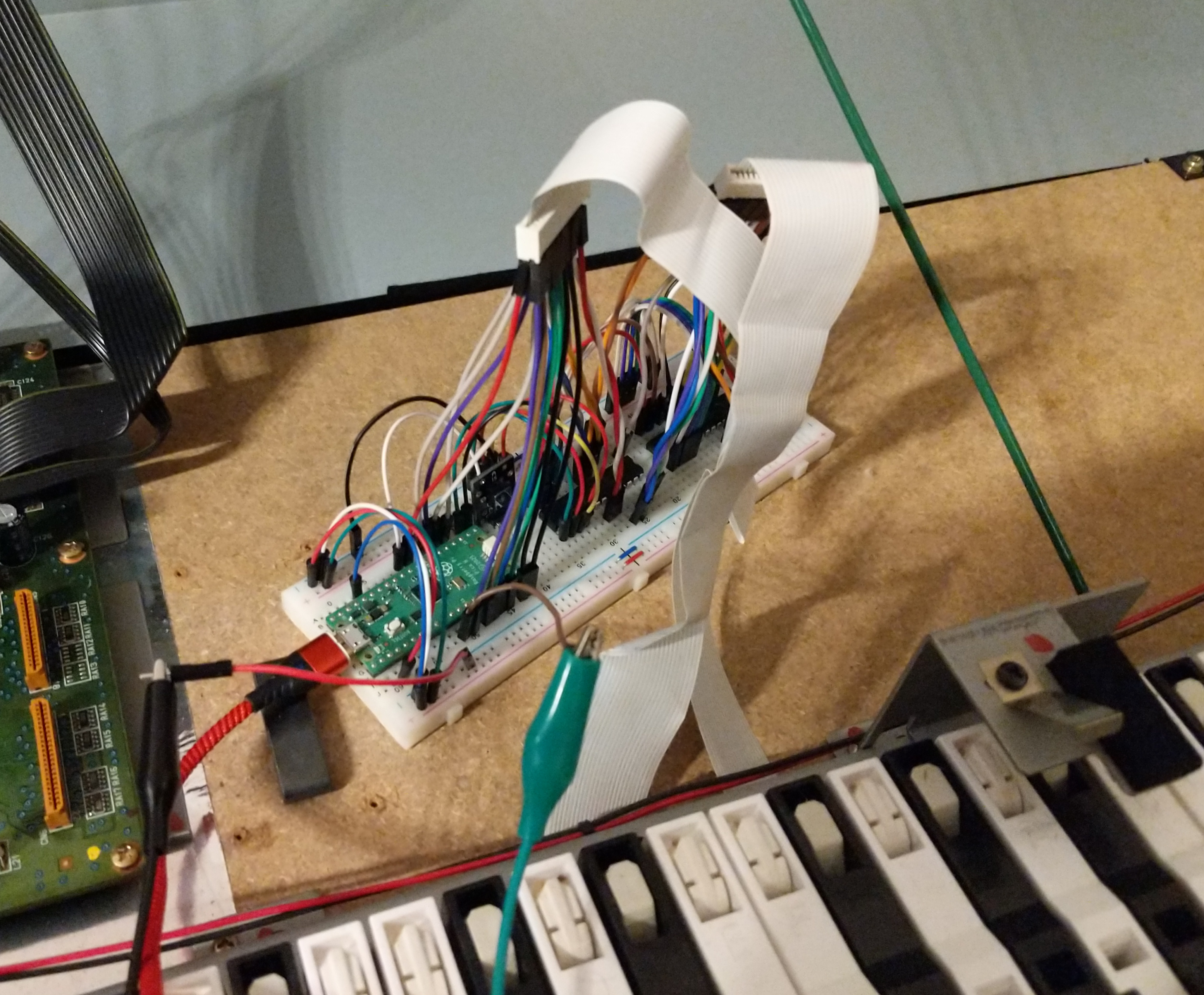
I used male-to-female jumpers with the female end trimmed to reveal the metal part inside. This was necessary to attach to the short pins on the jumpers. The opening in the plastic on the female end should face inwards when connected to the sockets.
Plugging this many jumper cables into a single socket can cause crosstalk.
Twisting cables and spacing them from each other may help prevent this.
To test for crosstalk, run pin_scanner and connect the socket contacts with each other with a jumper cable.
Each scan should return exactly two connections, these being the forward and reverse connection over the jumper cable.
If there are more connections, that means there is crosstalk.
Once the wiring is done, plug the ribbon cables from your piano into the sockets.
Using jumper wires and alligator clips, wire the Tip of the pedal's TRS jack into the GND rail. Then, wire the Ring (middle metal part, surrounded by two black bands), into the pedal pin (by default GP8). To attach the alligator clips to the TRS jack, you can strip the outer layer of a paperclip and wrap the metallic part around the jack. This works well for the Tip part, but for the Ring I use copper wire that is stripped.
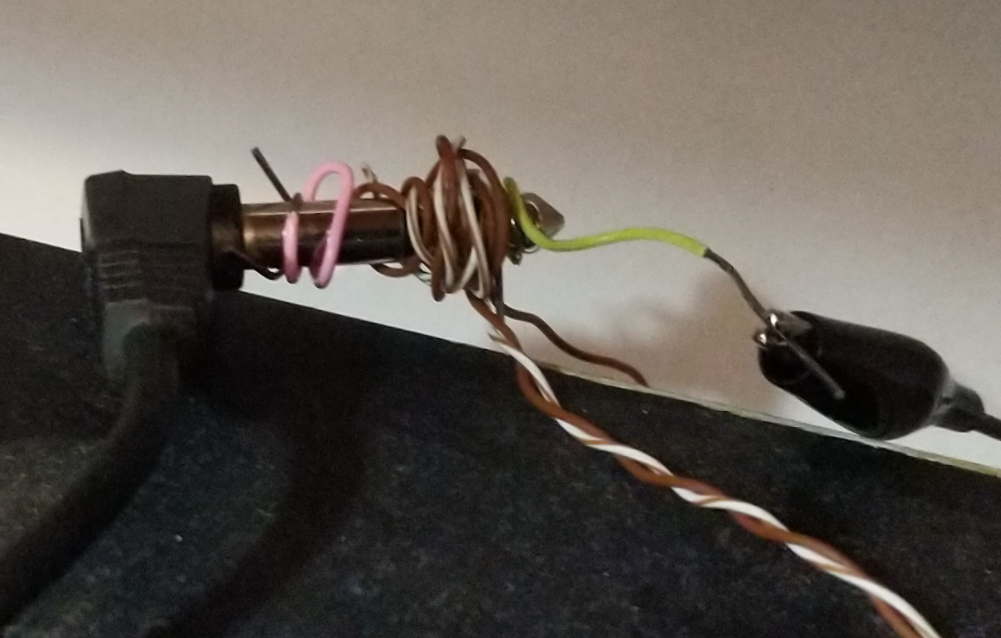
Because the sustain pedal is normally-closed, failure to wire this appropriately could result in the sustain pedal being constantly on.
To disable the sustain pedal, comment out the pedal_task in src/bin/piano_firmware.rs.