Here is project how to use 2x TLC5916 with 7-segment 2-digit LED display.

Board revision 1.0 (initial) is shown on picture.
Project status:
Board was tested successfully. See subproject Connecting TLC5916 to PC using LC 341A USB adapter for example.
Design files are in revision 1.1, 2019-03-10. New values of R1 and R2 were computed using this setup:
The relation between Rext and Iled is following (default configuration after power-up):
-
To get
I_ledin[mA]fromR_extin[kOhm]use:I_led = 1.25 * 15 / R_ext = 18.75 / R_extFor example (used in our circuit now):
R_ext = 1 [kOhm]=>I_led = 18.75 [mA] -
To get
R_extin[kOhm]fromI_ledin[mA]use:R_ext = 1.25 * 15 / I_led = 18.75 / I_ledFor example:
I_led = 20 [mA]=>R_ext = 0.937 [kOhm] = 937 [Ohm]
Also see Figure 4. Output Current vs Output Voltage in data sheet
to verify that VLED (voltage connected to common LED anode)
must be greater than Voltage drop on LED + 1V (roughly).
In our case using +5V voltage is OK.
Design was done in Eagle 9.3.0 Free
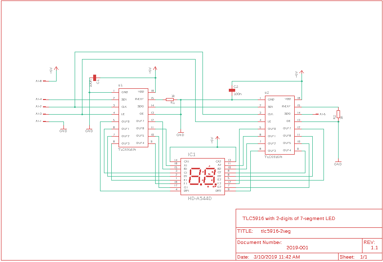
Schematic is:
Also in:
PCB design is:

Also in:
Following Eagle libraries were used:
- zlalanne/eagle-library for definition of TLC5916
- moje.lbr - my own part library (originally for Eagle 3/DOS) made in late 90's in college - used definition of 2-digit HD-A544D LED display
Board was made by gatema.cz for around 700 CZK (roughly 32 USD) including:
- 2 layers
- plated holes
- solder mask
- top silk screen
NOTE: Remember to follow instructions in eagle-dokumentace.pdf from Technicke informace (provided in Czech only)
- 2x TLC5916 - from tme.eu
- LED display HD-A544D - from gme.cz
- 2x 1K resistor - from my inventory
- 2x 100nF capacitor - from my inventory
- pinhead connector 6 pins in 1 row - used 20-pin DS1021-1x20SF1-10 - from gme.cz
There are following subprojects:
- Connecting TLC5916 to PC using LC 341A USB adapter - connecting this board to PC with USB adapter
Design shortcomings:
- digital signals (
CLK,SDI,SDO,LE) should be routed more carefully - not crossingLEDlines (where are high current spikes). - LED display power supply pins (
13and14) should be wired to+5Vsupply through jumper pins to allow custom power supply (for example+12V) different from main circuit+5Vpower supply.