Supermicro X9SCL+–F
The Supermicro X9SCL+-F is in-system-programmable, if standby power is applied with an ATX power supply.
The BMC's UART is exposed on the right pad of R1247 (TX) and R1162 (RX):
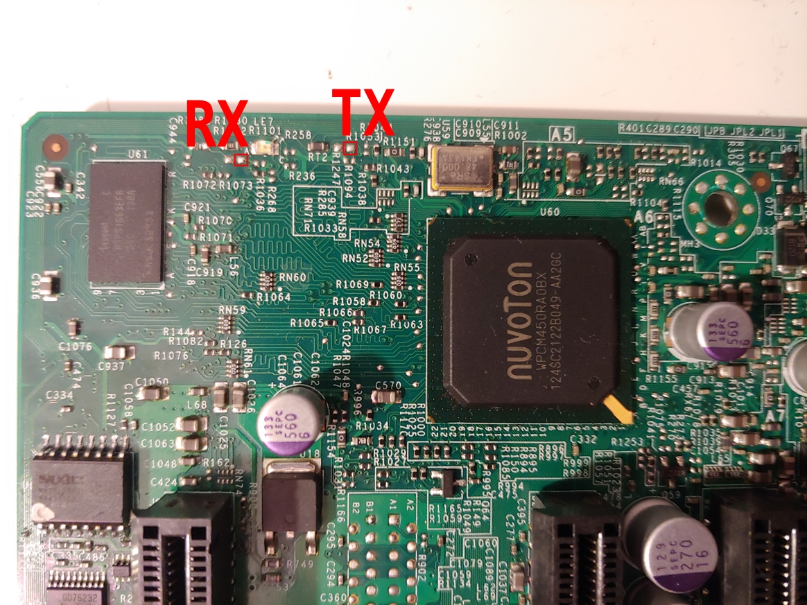 (photo of Supermicro X9SCL+-F revision 1.00)
BMC flash (U63):
- CLK - R1115
Host flash (U3):
U142 is a TLV3125 4-bit bus switch in TSSOP14 package.
- TLV3125: 1OE# - 2OE# - 3OE# - 4OE# - All output enables are controlled by the same signal
- U3 Vcc - U142 pin 14 (Vcc) - J29 pin 1 ("SPI programming" jumper)
- U3 CS# - U142 pin 11 (4B); U142 pin 12 (4A) - ???
- U3 DO - U142 pin 2 (1A); U142 pin 3 (1B) - ???
- U3 DI - U142 pin 6 (2B); U142 pin 5 (2A) - ???
- U3 CLK - U142 pin 8 (3B); U142 pin 8 (3B) - ???