This demo implements a point rendering and texture filtering technique called Surface Splatting1. More specifically, it implements the GPU accelerated surface splatting approach by Botsch et al.2 using OpenGL 3.3 (core profile). This basically comprises a raycasting based rasterization of elliptical splats, a deferred shading pipeline and an approximation to the original EWA filter1. The demo has been tested on a NVIDIA GTX 1080 Ti GPU using driver version 552.22 on Windows 10 (compiled with MSVC 2019) and 525.147.05 on Linux (compiled with GCC 12.2.0). It is built on top of GLviz and is therefore rather simple to compile.
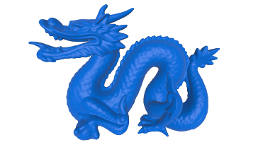
Left: Surface splatting of the Stanford Dragon model. Right: Closeup showing artificially shrunk splats to illustrate the splat distribution.
Before running CMake run either build-extern.cmd or build-extern.sh to download and build the necessary external dependencies in the .extern directory.
Surface splatting1 renders point-sampled surfaces using a combination of an object-space reconstruction filter and a screen-space pre-filter for each point sample. This effectively avoids aliasing artifacts and it guarantees a hole-free reconstruction of a point-sampled surface even for moderate sampling densities. The object-space reconstruction filter resembles an elliptical disk, also referred to as a splat, whose position, orientation, major axis, and semi-major axis are usually chosen to provide a good approximation to a given geometry. After a perspective projection of all splats to screen-space, rendering proceeds by applying a bandlimiting prefilter to avoid frequencies higher than the Nyquist frequency of the pixel sampling grid and summing up all contributions from the overlapping splats for each individual pixel with a subsequent normalization.
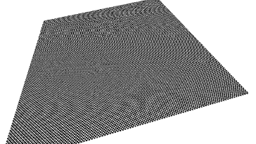
Surface splatting of a checkerboard. Left: EWA filter approximation enabled. Right: EWA filter approximation disabled.
Since today's GPUs are mostly optimized for triangle based rendering and do not provide any specialized fixed-function hardware for splat rasterization, it is required to use the programmable vertex and fragment shader units for this task. The most performant way to do so, at least on NVIDIA hardware, seems still to be to draw point primitives as screen-space squares of a certain size, and to cast a ray for each fragment to test whether it is part of the splat. While the corresponding formulas proposed by Botsch et al.3,2 are efficient to compute, they constitute only an approximation to the exact screen-space position and extents of a splat. Moreover, under certain conditions, the screen-space extents of a splat are underestimated by this approximation, which then causes rendering artifacts.
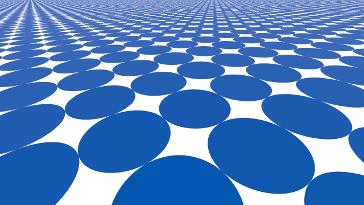
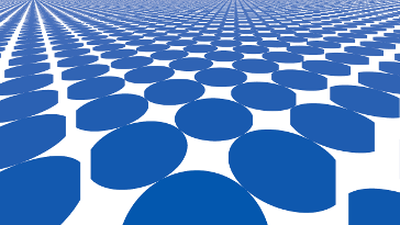
Left: Correct rendering. Right: Some splats are chopped off due to Botsch et al.'s2,1 approximation of the screen-space extents of a splat.
A very simple fix for this problem consists in multiplying the estimated splat extents with a safety factor larger than one, but this causes the generation of large number of unnecessary fragments and since the fragment stage is the performance bottleneck anyway, this is not a particularly good solution.
Computing the exact screen-space position and extents of a splat in a reliable and robust way turns out to be difficult in practice. For example, using the centralized conics approach of Zwicker et al.4, the resulting formulas involve the inverse of a 2D-to-2D projective mapping from a splats parameter space (given by the position of its center, and two vectors spanning the ellipse) to screen-space. The condition number of this mapping increases rapidly as the projection of a splat approaches a line. Zwicker et al.'s4 approach is therefore numerically unstable and plagued by large roundoff errors. The demo nevertheless also includes an implementation of this method.
In the context of GPU-based raycasting of quadric surfaces Sigg et al.5 noted that a reliable and robust solution to this problem must not use the inverse of the projective mapping. This is indeed possible by exploiting the fact that normal vectors, as opposed to ordinary vectors, transform by the inverse transpose of a mapping. The underlying idea is to find a plane in screen-space which is tangent to a quadric in its parameter space, i.e. tangent to the unit sphere. Mathematically, this requires the solution of a quadratic equation for each dimension and does not involve the inverse projective mapping. Weyrich et al.6 later adapted this method to the special case of surface splatting. It is important to note that this approach yields a splats position and extents in screen-space, i.e. normalized device coordinates. It is therefore not possible to clip the obtained bounding box by the view-frustum. Furthermore, while conics are closed under projective mappings, the perspective projection of an ellipse may yield a parabola or hyperbola, in which case the proposed method does not work anymore. To avoid these problems, my implementation considers only those splats whose bounding sphere intersects with the view-frustum.
Closeup of a cube consisting of 24 clipped splats. Left: Using my method of a projected bounding polygon produces a correct image. Right: Using the method proposed by Weyrich et al.6 produces artifacts.
In the course of implementing and analyzing all these methods, I also devised my own approach. The idea is to bound a splat by a polygon in its parameter space and to only employ this bounding polygon to compute the screen-space position and extents of a splat. To this end, the polygon is first transformed to clip space where it is clipped by the view-frustum using the Sutherland-Hodgman algorithm. A perspective division of each vertex then yields the clipped polygon in screen-space where the desired quantities are simple to compute. This method is not exact, but it produces a correct upper bound to the extents of a splat and unlike previous methods also works for large splats being close to the near plane.
The demo also implements clipped splats4 to facilitate the rendering of sharp features like edges and corners of a cube.
Left: Surface splatting of a cube consisting of 24 clipped splats. Right: Cube with artificially shrunk splats to illustrate the splat distribution.
[1] Zwicker M., Pfister H., van Baar J., Gross M.: Surface Splatting. In Proceedings of the 28th Annual Conference on Computer Graphics and Interactive Techniques, SIGGRAPH '01, pp. 371-378.
[2] Botsch, M., Hornung, A., Zwicker, M., Kobbelt, L.: High-Quality Surface Splatting on Today's GPUs. In Proceedings of Eurographics Symposium on Point-Based Graphics, 2005, 17-24.
[3] Botsch, M., Spernat, M., Kobbelt, L.: Phong Splatting. In Proceedings of the First Eurographics Conference on Point-Based Graphics 2004, SPBG '04, 25-32.
[4] Zwicker, M., Räsänen, J., Botsch, M., Dachsbacher, C., Pauly, M.: Perspective Accurate Splatting. Proceedings of Graphics Interface, 2004, GI '04, 247-254.
[5] Sigg, C., Weyrich, T., Botsch, M., Gross, M.: GPU-based Ray-casting of Quadratic Surfaces. Proceedings of the 3rd Eurographics / IEEE VGTC conference on Point-Based Graphics, 2006, SPBG '06, 59-65.
[6] Weyrich, T., Heinzle, S., Aila, T., Fasnacht, D. B., Oetiker, S., Botsch, M., Flaig, C., Mall, S., Rohrer, K., Felber, N., Kaeslin, H., Gross, M.: A Hardware Architecture for Surface Splatting. ACM Transactions on Graphics, 2007.

