= Girier
Useful links
https://sylvainzimmer.com/blog/2021/09/smart-plugs-tasmota/ https://blakadder.com/disassembling-CN39/ https://community.home-assistant.io/t/solved-girier-16a-power-monitoring/393192 https://www.esphome-devices.com/devices/Awow-EU3S-Power-Monitoring-Plug https://www.esphome-devices.com/devices/RGB-Smart-Plug-16A-Power-Monitor https://tasmota.github.io/docs/Power-Monitoring-Calibration/ https://templates.blakadder.com/girier_JR-PM01.html
GPIO # Component GPIO00 None GPIO01 LedLink GPIO02 None GPIO03 HLWBL SELi GPIO04 BL0937 CF GPIO05 HLWBL CF1 GPIO09 None GPIO10 None GPIO12 Relay1 GPIO13 Button1 GPIO14 Led1i GPIO15 None GPIO16 None FLAG None
Step 2: Identify the right pins There are slight differences between ESP8266 boards and their pins will not always be mapped to the same functions. This mapping is called a pinout.
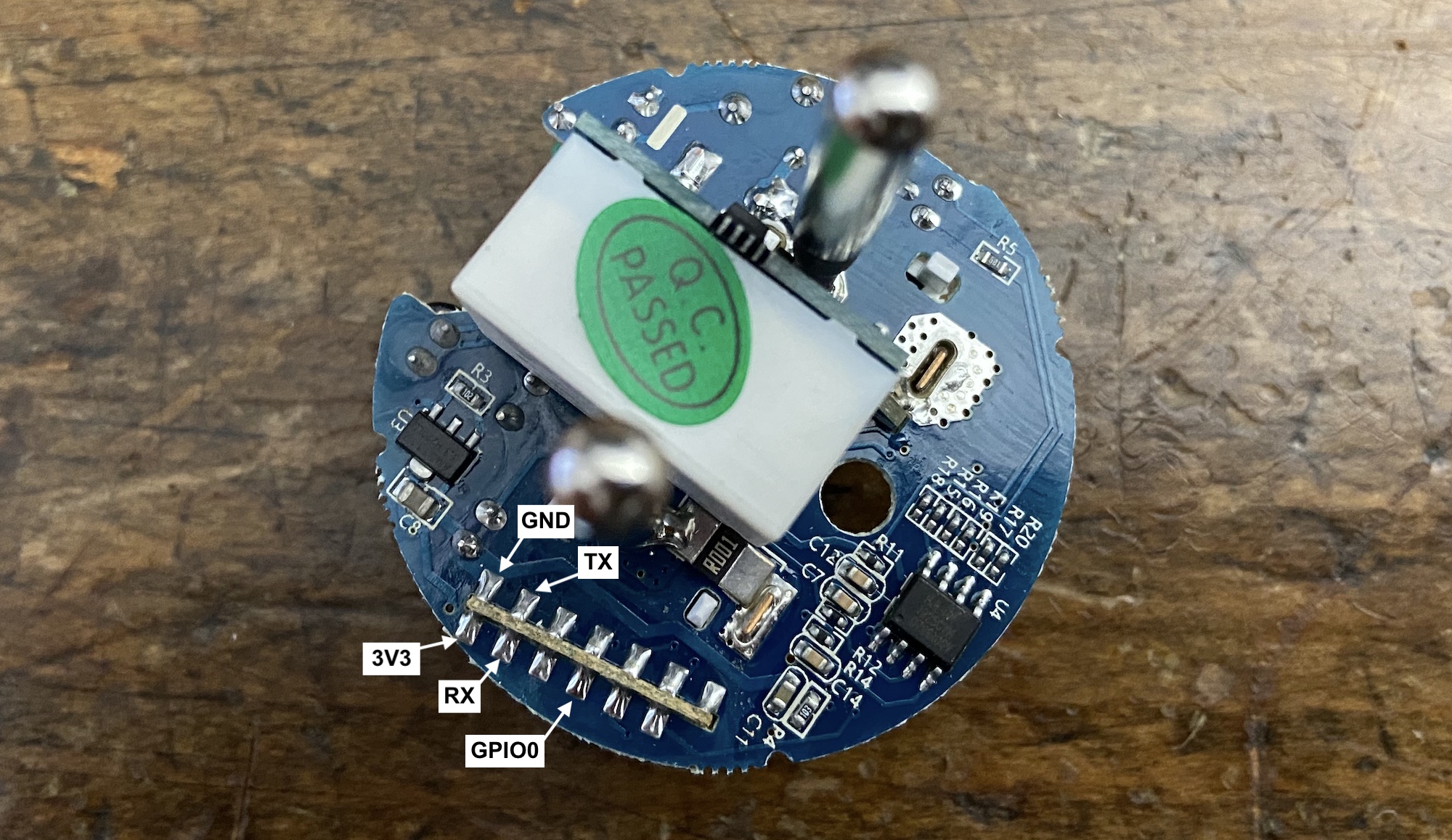
The best way to find the pinout of your specific board is to google any reference you can find written on it. In my case, it led me to this comment on GitHub which helped me build this pinout:
Elehot AWP16L pinout