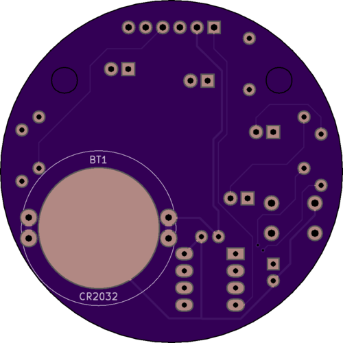
This project provides a simple electronic device that students of varying ability, with some supervision, should be able to assemble within about half an hour. The targeted materials cost of each badge is less than US$10.
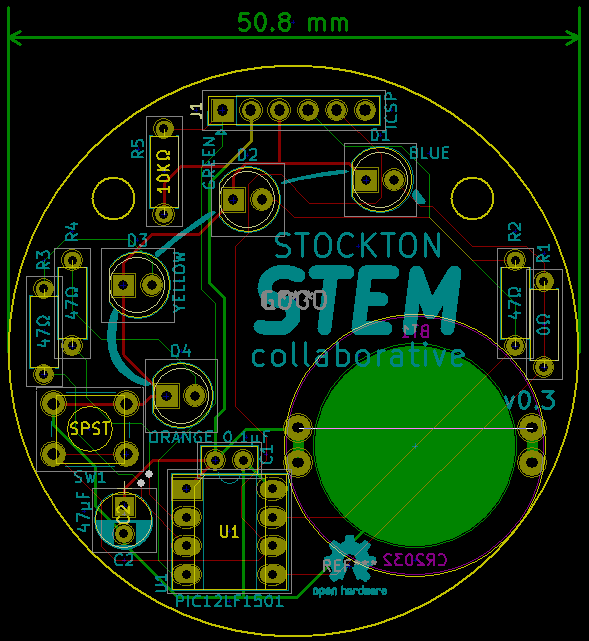
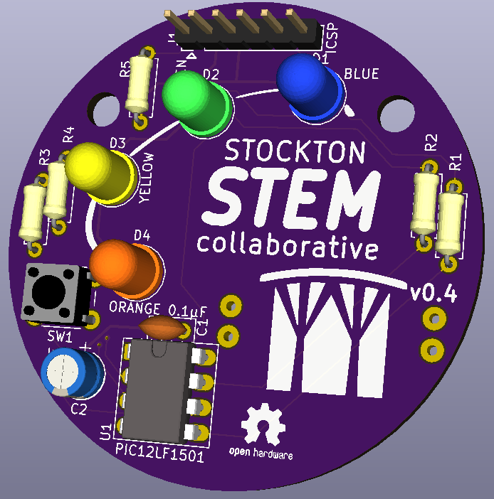
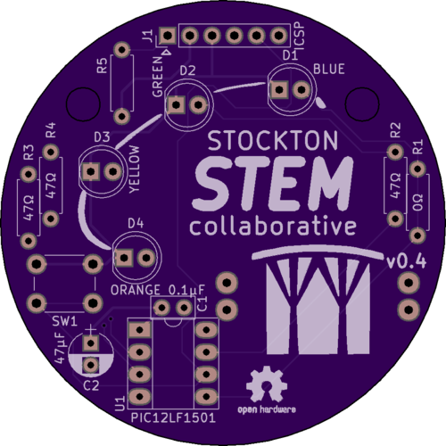
The printed circuit board is made to resemble the Stockton STEM logo in the form of a badge with LEDs in place of the colored circles.
The device is sophisticated enough that more advanced students should then be able to modify its functions using the source code in this repository, the free version of the development software and an inexpensive device programming tool.
The board design schematics and firmware source code lives at https://github.com/stockton-stem/stockton-stem-badge and an assembly guide document is available under releases.
The Stockton STEM Collaborative page lives at https://stockton.edu/stem.
Components:
- Printed circuit board.
- 8-pin microcontroller chip.
- Capacitors.
- Resistors.
- LEDs of different colors.
- Coin-cell battery.
- Push-button.
v0.3 of the board has had an outing with over 40 7th and 8th graders graders!
The microcontroller in this project, a MicroChip PIC12LF1501, is a small 8-pin device with a number of hardware features. It was selected for this project specifically because of its size, its very low power consumption and having four PWM peripherals. Additionally it helps that, like many PIC devices, it is quite inexpensive.
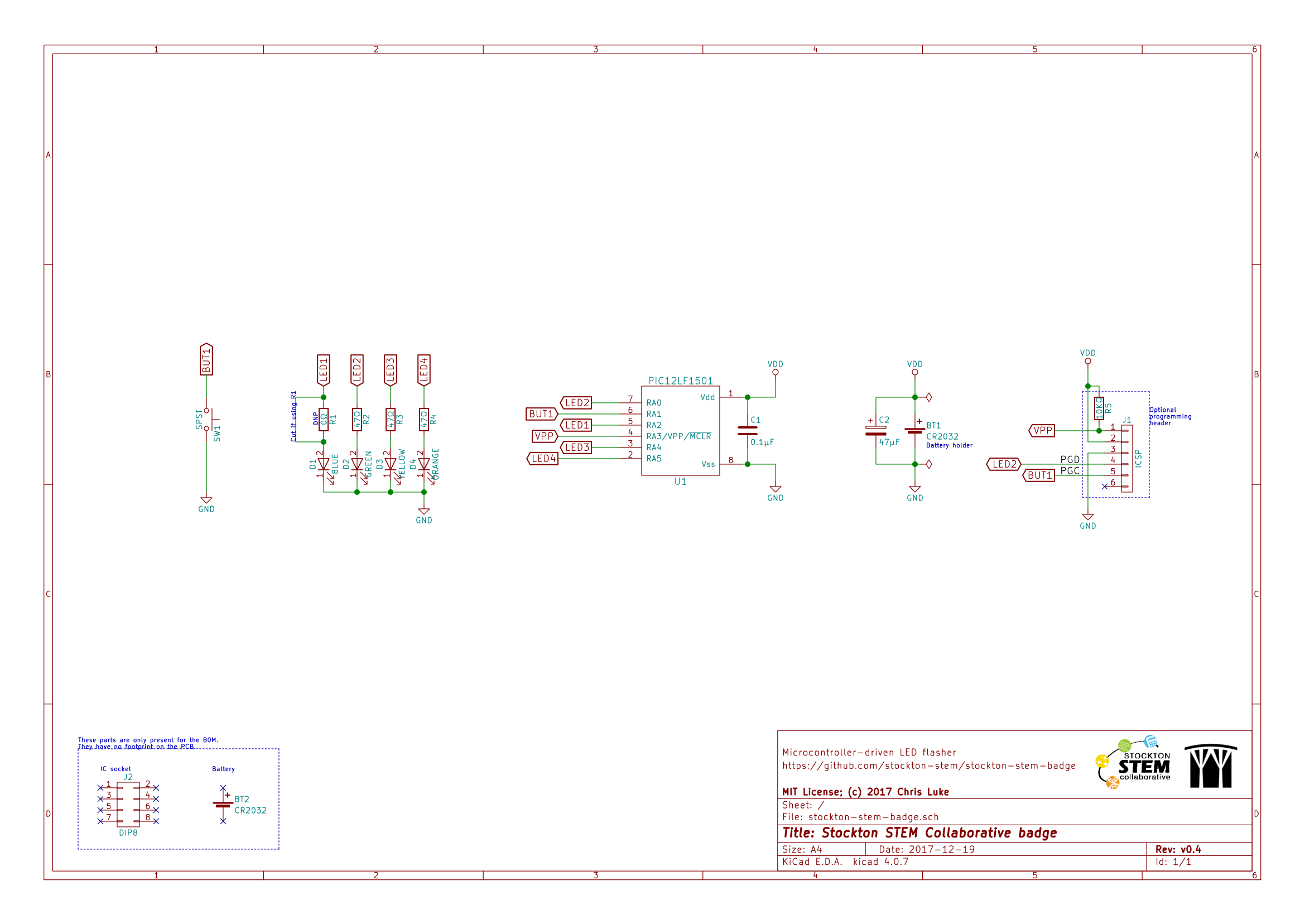
The circuit for the project uses four differently colored LEDs (and associated current-limiting resistors), a button, and is powered by a coin-cell battery. Two capacitors provide decoupling and bulk storage; the latter helps reduce smooth the otherwise bursty current draw of the LEDs from the battery. The board has locations to optionally also provide an ICSP programming header and associated pull-up resistor.
The code for this project is divided roughly across a handful of source files.
main.c contains the basic hardware device initialization and the interrupt
handler. badge.c and badge.h contains the code with LED patterns in it.
Various configuration details are kept in config.h (Peripheral setup values,
for example to setup the timers and PWMs) and pic_config.c (PIC startup
values).
Power is derived from a single CR2032 button-cell battery nominally providing 3v. The specifications for this type of battery vary a little but generally speaking they are designed to provide a limited amount of current for a fairly long time. Design capacity is typically 225mAh with sustained maximum current of between 0.2 to 1mA and with peak current of as much as 15mA but not for more than a few milliseconds.
The observant will note we have four LEDs on this board and typical LEDs have a forward current of ~20mA each. Whilst most CR2032's we have used, including no-name brand varieties, have been able to provide sufficient current to drive all four LEDs at full brightness, it is not without significant drop in the voltage the cell provides (a fresh cell may drop to 2.6v, for example) but it will also quickly deplete the capacity of the battery. For this reason our software will need to try to avoid powering the LEDs for extended periods and also avoid powering the LEDs at full brightness. Indeed, the bulk storage capacitor, C2, is provided entirely as an energy store that charges during the off-section of the PWM duty cycle to reduce the demand for peak current from the battery. It is this consideration that also directed the need for a button in the design, so that the device may be woken up after having gone to sleep after some short period of activity.
Why then, given the limitations, did we choose a CR2032? Simply, they are readily available, inexpensive, a usable form factor and mounting in the design is straightforward. The tradeoff is capacity, but for this project this currently seems acceptable.
The internal CPU clock (Fosc) is configured to run at 1MHz. At a later stage the clock may be configured at a lower rate to reduce battery consumption, though all downstream modules driven by this clock then need to be considered and their values amended.
The four PWM peripherals drive the pins that the LEDs are wired to. Pulse- width modulation enables the project to control the brightness of the LEDs. Each PWM peripheral has its own duty-cycle value which sets the brightness. The four PWM modules share the same clock input which is generated by the Timer 2 peripheral. This is in turn sourced from the internal oscillator though a divider. These are configured to provide a 16.26ms PWM period (about 600KHz). In future, reducing the system clock will reduce this PWM clock; LEDs may use less, or more, power with a slower PWM period and this should be investigated.
Timer 1 is setup to generate an interrupt every two seconds and is driven from
a separate internal oscillator that runs at 32KHz. The interrupts are counted
and after RUN_INTERVAL seconds (see config.h) the project is powered off.
This involves disabling the PWM modules, turning off the LEDs, disabling any
interrupts that might wake the device prematurely and then putting the system
to sleep. In this state the processor uses the least amount of power possible;
a fresh CR2032 battery might last more than two years at this power level.
The button is connected to GPIO RA1 on pin 6 of the device. In software we
configure this as a digital input with a built-in "weak pull-up"; that is,
the device provides a (software removable) resistor between the input and Vdd.
When left open-circuit, the input will read a digital 1. The button pulls the
input to ground, and thus to digital 0.
Any interrupt can wake the device from sleep if it is left configured when going to sleep and any associated peripheral remains running when sleeping.
The input pin is configured to "interrupt on change"; this mode will survive sleeping. Should the input line change when asleep the system resumes from where it left of; the code re-initializes the hardware and then the program continues as normal.
The interrupt also triggers during normal operation when the button is pressed; this does two things:
- It resets the runtime counter, thus extending the time the project will run for.
- It is also used to cycle through the various LED patterns available.
To de-bounce the input from the button, Timer 0 is setup to run once when the button interrupt fires. Timer 0 is setup to generate an interrupt in about 16ms after being started, typically enough time for any noisy input signals from the button to have finished; each subsequent noisy input resets the Timer 1 counter. Once the Timer 1 counter completes, its interrupt then causes the LED pattern to cycle by incrementing the pattern number.
A hardware debounce would be much simpler to implement, a small capacitor and a resistor would achieve it; we prioritize the need to keep the component count down over code size. Similarly a stronger pull-up is typically desirable; keeping component count down is part of the reason we use the built-in but since this pin is the ICSP clock pin an external pull-up could easily interfere with device programming.
LED patterns are produced by a function that is expected to set the state of the LEDs once and then return; advancing to the next LED state the next time it is called. In this way cycling through different LED patterns is just a matter of the dispatching code sitting in a loop and on each iteration checking which pattern should be running and calling the appropriate function.
Presently this dispatch is performed using a function table and an index value that is incremented when the button is pushed, wrapping to zero when the it exceeds the number of entries in the table.
Adding a new pattern is a simple matter of writing a new iterator function
in badge.c and adding that function to the array badge_iterator in
badge.c.
In future, power reduction may be realized by replacing the current per- iteration spin-style sleep (that is, the processor executes dummy instructions in a loop until the correct amount of time has passed) with a system sleep that is woken up by Timer 0 after N-milliseconds, though in the scheme of things the amount of power consumed by the processor is tiny compared to the LEDs.
Several tools, a mixture of hardware and software, are needed to develop, build and install new code onto the PIC processor.
http://www.microchip.com/mplab/mplab-x-ide
This is an integrated development environment (IDE) from Microchip. It is available for Linux, MacOS X and for Windows from the Downloads tab.
http://www.microchip.com/mplab/compilers
This is a proprietary compiler from MicroChip designed for their 8-bit PIC series. It integrates effortlessly with the MPLAB-X IDE. It is available for Linux, MacOS X and for Windows. There are several XC compilers available on the Downloads tab, for this project MPLAB XC8 is required.
The paid-for license enables enhanced compiler optimizations that can reduce the produced firmware image size and the code may run more efficiently; whilst nice these are not needed for this project and thus the free license is perfectly adequate.
To program new code onto the PIC a programmer is necessary. MicroChip have their own mechanism for this known as ISCP; either one of the two programmers below will suffice for this. Note that older PICkit 2 programmers, or those that are PICkit 2 compatible, will not work on the PIC in this project.
This particular PIC chip also does not have a built-in debugger; for that an external module is required in addition to one of the programmers below; this is strictly optional.
When a programmer is connected the push-button may not always work as expected; given the low pin count of the processor two of the signals needed for ICSP are shared with other functions; for this project that means one LED and the button. When programming you may notice the green LED flashing. Some programmers hold the line used for the button low after programming thus interferes with its operation.
Whatever programmer is used, ensure that it is configured with a target voltage of 3.0v. The current limiting resistors of the LEDs are chosen with the 3v supplied by a button cell in mind; any more than this can damage the LEDs.
http://www.microchip.com/pickit3
This USB device is a basic ICSP PIC programmer that typically retails for $50US though cheaper versions, of varying authenticity, are available on Ebay and elsewhere for $10-$20.
The pull-up resistor R5 is required for this programmer to function correctly.
This is an enhanced ICSP PIC programmer and debugger. It is faster and can provide more power to target boards; it is also much more expensive at about US$200.
Empirical observations suggest that the pull-up resistor R5 may be optional for this programmer to function correctly.
This is not strictly necessary but it can often aid debugging new code if a hardware debugger is available. This device sells for US$50. You insert it into the target board instead of the normal PIC and the programmer then plugs into this debugging module. It only provides a single hardware breakpoint but given the simplicity of this project that should prove sufficient for most debugging.
MIT License
Copyright (c) 2017 Chris Luke
Permission is hereby granted, free of charge, to any person obtaining a copy of this software and associated documentation files (the "Software"), to deal in the Software without restriction, including without limitation the rights to use, copy, modify, merge, publish, distribute, sublicense, and/or sell copies of the Software, and to permit persons to whom the Software is furnished to do so, subject to the following conditions:
The above copyright notice and this permission notice shall be included in all copies or substantial portions of the Software.
THE SOFTWARE IS PROVIDED "AS IS", WITHOUT WARRANTY OF ANY KIND, EXPRESS OR IMPLIED, INCLUDING BUT NOT LIMITED TO THE WARRANTIES OF MERCHANTABILITY, FITNESS FOR A PARTICULAR PURPOSE AND NONINFRINGEMENT. IN NO EVENT SHALL THE AUTHORS OR COPYRIGHT HOLDERS BE LIABLE FOR ANY CLAIM, DAMAGES OR OTHER LIABILITY, WHETHER IN AN ACTION OF CONTRACT, TORT OR OTHERWISE, ARISING FROM, OUT OF OR IN CONNECTION WITH THE SOFTWARE OR THE USE OR OTHER DEALINGS IN THE SOFTWARE.

