-
Notifications
You must be signed in to change notification settings - Fork 5
GoodTag10

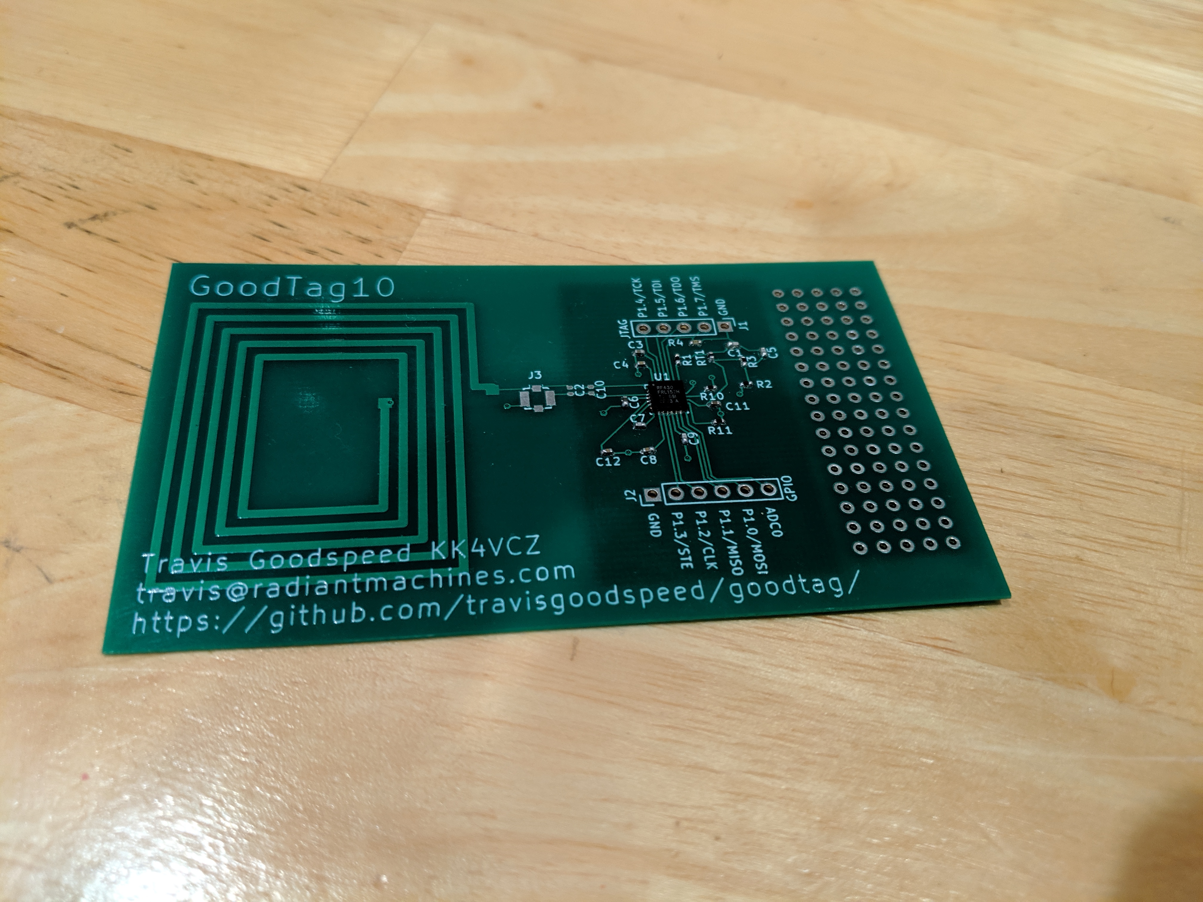
The GoodTag10 is my first attempt at an RF430FRL152H device. It communicates by NFC Type V, powered by the reader device, and includes a prototyping area and temperature sensor for development.

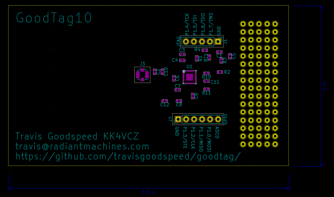
Assembly is pretty straightforward. None of the 0402 passive components are directional, and the RF430 chip is oriented with its text the same way as the silkscreening.
Please note that while a battery appears on the schematic, it does not exist in the layout. J3 is an SMA connector that is only used for tuning the antenna, so you probably don't need it.
Designator	Package			QTY	Designation		Digikey
U1		RF430FRL152H		1	RF430FRL152		296-42545-1-ND
C1,C5		0402 (1005 metric)	2	22pF			311-1018-1-ND
RT1		0402 (1005 metric)	2	100K Thermistor		490-2404-1-ND
R3		0402 (1005 metric)	2	100K			P100KDECT-ND
R1,R2		0402 (1005 metric)	2	1K			YAG1234CT-ND
C2		0402 (1005 metric)	1	91pF			311-3756-1-ND
R10,R11		0402 (1005 metric)	2	0R			RMCF0402ZT0R00CT-ND
R4		0402 (1005 metric)	1	10K			RR05P10.0KDCT-ND
C3,C4,C8,C12	0402 (1005 metric)	4	100nF			1276-1004-1-ND
C11		0402 (1005 metric)	1	1µF			1276-1235-1-ND
C7,C9		0402 (1005 metric)	2	10nF			311-1014-1-ND
C6		0402 (1005 metric)	1	2.2µF			587-3153-1-ND


Notes:

1) Do not populate the pin headers or the U.FL antenna connector.

2) The sum of C2 and C10 should be roughly 88pF.  I used four 22pF
   caps to verify this, but one 91pF cap on C2 will probably work just
   fine when C10 is not populated.

3) R10 and R11 are listed as zero Ohm, but larger values probably
   wouldn't hurt.  Later revisions might drop one or both of them for
   wire traces.

4) This first revision of the PCB does not support a battery.  Later
   versions might add an optional one.

5) The RF430FRL152 is the most featureful, but in mass production for
   a specific application, you can probably save some money by
   substituting the FRL153 or 154.
After assembly, the GoodTag is immediately functional thanks to the RF430FRL152H's mask ROM. Use the GoodV app in Android to flash firmware to the device.
Although JTAG pins are broken out on this board, they run at 1.5V and require level conversion from the Texas Instruments debugger.

Schematics are available as goodtag10.pdf. An authoritative BOM, Kicad design files, and Gerbers are available in the Git repository.