Logic designed using an explicit finite state machine Verified using assertions/constrained randomized stimulus in testbench, and synthesized on a Cyclone® V FPGA
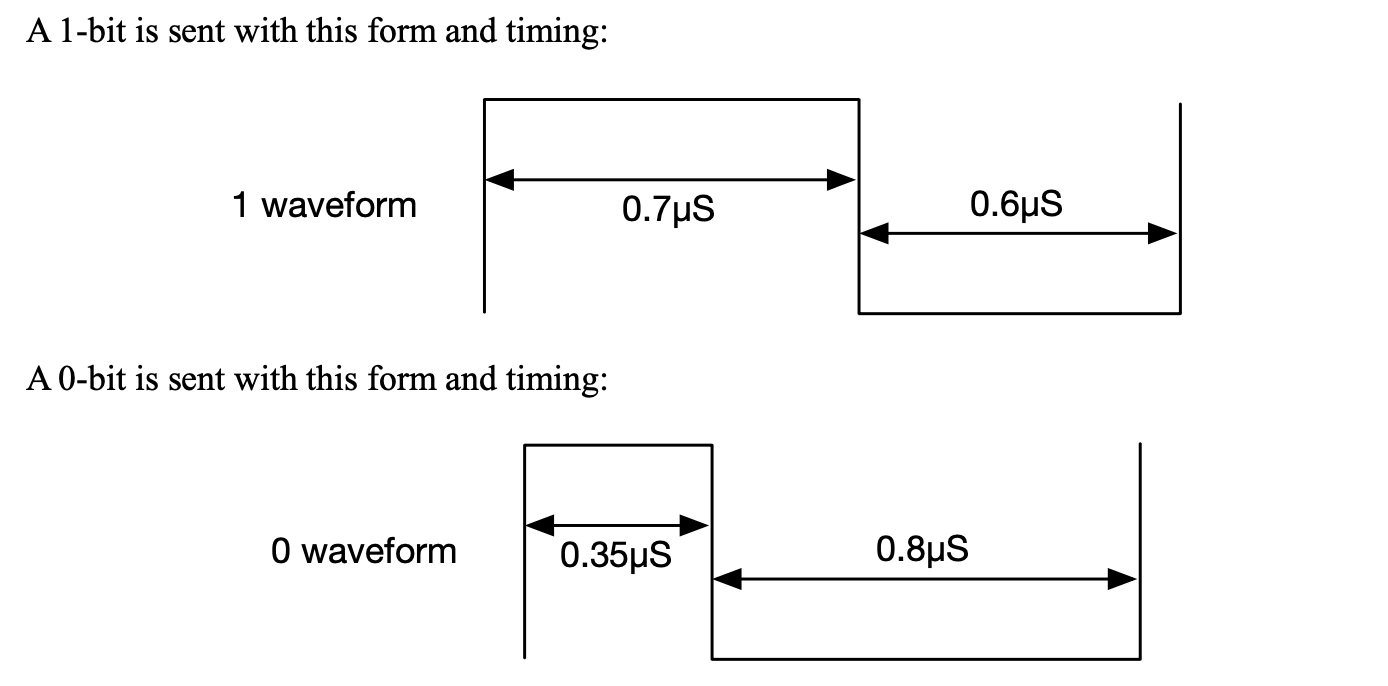
The string of LEDs responds to a serial, pulse width modulated waveform. Each bit is sent according to the waveform:
24 contiguous bits form an LED command. Each of the three bytes controls the intensity of the red, green, and blue colors.
A display packet is made of multiple LED commands, one for each LED in the string. 50 microseconds must be waited before sending another display packet. The illustration below shows a single LED command, consisting of 24'hF08025, followed by a space and the beginning of the next display packet.

Pin GPIO_0[1] is a general purpose I/O pin connected to the serial output that drives the LED strip
Physical hardware connections to the FPGA switches/keys, synthesized with Quartus II Prime software Four different modes based on Switches/keys
- Regular LED mode One random color shows up at a time (no SW activated)
- Neon SW[1] && ~SW[2] Alternates between several neon displays, updates simultaneously
- Rainbow display: SW[1] && SW[2] Fixed rainbow display
- Christmas Mode: SW[2] && ~SW[1] Red/green on every other pixel, back and forth blinking
Finite state machine logic to send bitstream given load/send signals from the Task2 hardware thread
Testbench (assertions, constrained randomized tests) to test and simulate sending patterns to the LED strip for verification purposes
Hardware thread, tells NeoPixelController to load/send Color Module tells it which color/pattern to use Different patterns: Neon, Christmas, Rainbow, Regular
Datapath elements (counters, registers)