Board configuration
Some modules require setting up pins correctly, configuring on-board peripherals and/or triggering the module to turn it on. Here is a list of some popular GSM modules. If your board is missing and you have problems connecting, please refer to documentation (provided by the manufacturer).
P.S. If you want to add more modules here, please open an issue and specify all the needed information.

GSM 1400 board defines SerialGSM serial and GSM_DTR, GSM_RESETN pins that are used to control the GSM module:
#define TINY_GSM_MODEM_UBLOX
#include <TinyGsmClient.h>

#define SerialAT SerialGSM
...
void setup() {
  ...
  SerialAT.begin(115200);

  pinMode(GSM_DTR, OUTPUT);
  digitalWrite(GSM_DTR, LOW);
  delay(5);

  // Turn on the GSM module by triggering GSM_RESETN pin
  pinMode(GSM_RESETN, OUTPUT);
  digitalWrite(GSM_RESETN, HIGH);
  delay(100);
  digitalWrite(GSM_RESETN, LOW);
  ...

}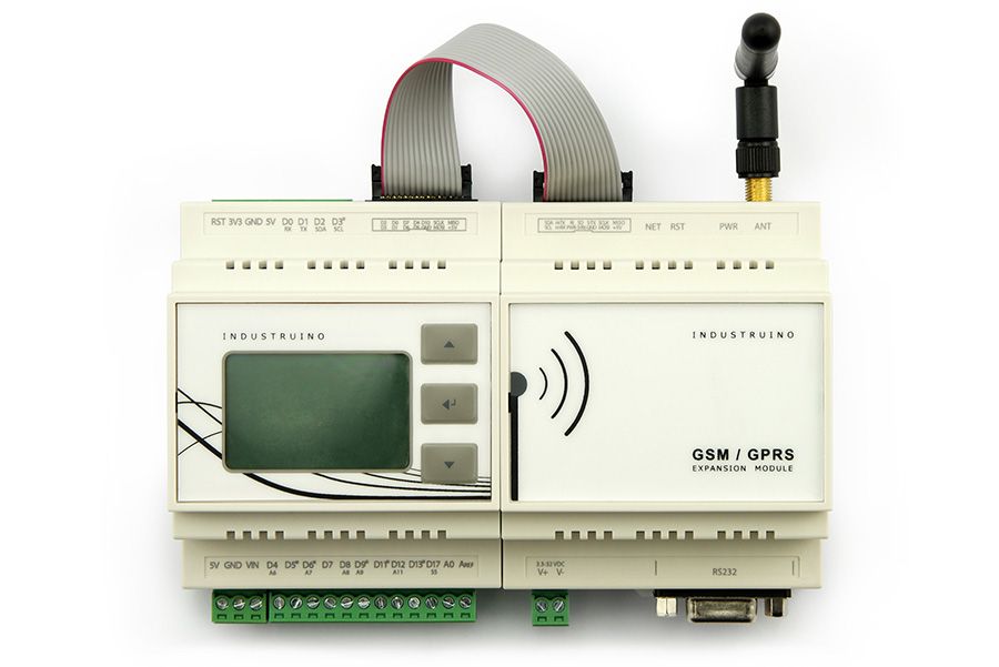
Industruino GSM allows selecting Serial1 or Serial with an on-board jumper. Pin 6 is used to turn it on and off.
#define TINY_GSM_MODEM_SIM800
#include <TinyGsmClient.h>

// Select Serial1 or Serial depending on your module configuration
#ifndef __AVR_ATmega328P__
#define SerialAT Serial1
#endif
...
void setup() {
  ...
  SerialAT.begin(115200);

  // Turn on the GSM module with 1 second pulse on pin 6
  pinMode(6, OUTPUT);
  digitalWrite(6, HIGH);
  delay(1000);
  digitalWrite(6, LOW);
  ...
}
Board configuration is taken directly from documentation:
#define TINY_GSM_MODEM_A7
#include <TinyGsmClient.h>

#ifndef __AVR_ATmega328P__
#define SerialAT Serial1
#endif
...
void setup() {
  ...
  SerialAT.begin(115200);

  // Set up the GSM module
  pinMode(4, OUTPUT);
  pinMode(5, OUTPUT);
  pinMode(8, OUTPUT);
  digitalWrite(5, HIGH);
  digitalWrite(4, LOW);
  digitalWrite(8, LOW);
  delay(2000);
  digitalWrite(8, HIGH);
  delay(3000);
  ...
}
Hologram Dash communicates with the GSM module via System microcontroller. Interestingly, it supports the Passthrough mode, that allows communicating with the GSM module directly. The only small issue is that the modem variable is already occupied by the core library, just pick another name for your modem, like myModem.
Note: This was tested with a 3rd party SIM only.
#define TINY_GSM_MODEM_UBLOX
#include <TinyGsmClient.h>

#define SerialAT SerialSystem
...

TinyGsm myModem(SerialAT);  // Can't call it just 'modem', results in a name clash

void setup() {
  ...
  // Set up Passthrough
  HologramCloud.enterPassthrough();  // No need to select the baud rate, etc.
  delay(1000);
  ...
}
Board configuration is taken directly from documentation:
#define TINY_GSM_MODEM_SIM800
#include <TinyGsmClient.h>

#define SerialAT Serial2
...
void setup() {
  ...
  SerialAT.begin(115200, SERIAL_8N1, 26, 27);

  // Set up the GSM module
  pinMode(4, OUTPUT);
  pinMode(5, OUTPUT);

  digitalWrite(4, LOW);
  digitalWrite(5, HIGH);

  delay(2000);
  ...
}
If you like TinyGSM library - give it a star, or fork it and contribute!

