MainLightShadow
这一章节主要内容是在SRP中实现平行光源(Directional Light)的实时阴影渲染。
这里使用Shadow Mapping技术来实现。 相关理论文章可以参考:
要实现平行光阴影,一般分如下两个步骤:
- Shadow Caster (阴影投射)
- Shadow Receiver (阴影接收)
阴影投射从平行光的角度,以正交摄像机绘制场景,得到一张深度图,作为ShadowMapTexture
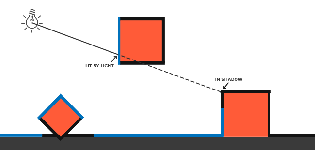
如上图所示,蓝色线条为灯光照亮区域,而黑色部分由于被遮挡形成阴影区域。其中蓝色部分会渲染到ShadowMapTexture中。
从摄像机角度绘制场景时,在Fragment里,我们重建每个像素的世界坐标,然后重投影到灯光的ShadowMap空间,与ShadowMapTexture中记录的深度值做比较。从而得出像素是否在阴影区域。
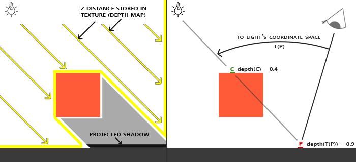
如上图,在ShadowCaster阶段,C点深度0.4会被记录到ShadowMapTexture中。 然后当摄像机渲染P点时,算得P点重投影到ShadowMap后的深度为0.9, 意味着被C点遮挡,因此判定在阴影区域。
下面使用SRP来分别实现Shadow Caster和Shadow Receiver。
要实现Shadow Caster, 可以细分为如下几个步骤:
- 对场景中的灯光进行裁剪,仅保留对当前摄像机可见区域有影响的灯光.
- 计算灯光的View矩阵和Project矩阵
- 根据计算好的View、Project矩阵,从灯光角度渲染场景,得到ShadowMapTexture
这里我们专门为Shadow Caster定义一个Pass类:
public class ShadowCasterPass{

    public void Execute(ScriptableRenderContext context,Camera camera,ref CullingResults cullingResults,ref LightData lightData){

    }
}在SRP中,复杂的裁剪工作,引擎已经做好了内部实现,我们只需要通过调用ScriptableRenderContext.Cull这个API来进行进行。
在这个系列的前两章中,我们已经完成了裁剪工作,并得到了CullingResult对象和LightData对象。我们将这两个对象从RenderPipeline中,通过ShadowCasterPass.Execute传递过来。其中LightData对象定义如下:
public struct LightData{
    public int mainLightIndex;
    public VisibleLight mainLight;
}
在Shadow Caster Pass里我们需要进一步判定,该灯光是否会对可视区域投下阴影。 在SRP中有如下API:
public bool CullingResults.GetShadowCasterBounds(int lightIndex, out Bounds outBounds);该接口会根据摄像机视锥裁剪结果,针对指定灯光计算其Shadow Caster影响范围,并返回一个BoundingBox。 假如在范围中没有一个阴影投射对象,那么返回false。
因此我们使用此接口来做前置判断:
//false表示该灯光对场景无影响,直接返回
if(!cullingResults.GetShadowCasterBounds(lightData.mainLightIndex,out var lightBounds)){
    return;
}SRP中提供了如下接口来做这件事:
public bool CullingResults.ComputeDirectionalShadowMatricesAndCullingPrimitives(int activeLightIndex, int splitIndex, int splitCount, Vector3 splitRatio, int shadowResolution, float shadowNearPlaneOffset, out Matrix4x4 viewMatrix, out Matrix4x4 projMatrix, out Rendering.ShadowSplitData shadowSplitData);可以看到,这个接口的参数非常之多。在这里,我们暂且不去管split相关的参数。因此只需要关注如下三个输入参数:
- activeLightIndex 即我们前面拿到的平行光源索引
- shadowResolution 为ShadowMap贴图的分辨率
- shadowNearPlaneOffset 灯光角度对场景进行深度渲染时的近平面
shadowResolution 可以从Light组件中获取,我们定义如下:
private static int GetShadowMapResolution(Light light){
    switch(light.shadowResolution){
        case LightShadowResolution.VeryHigh:
        return 2048;
        case LightShadowResolution.High:
        return 1024;
        case LightShadowResolution.Medium:
        return 512;
        case LightShadowResolution.Low:
        return 256;
    }
    return 256;
}
shadowNearPlaneOffset同样可以从Light组件获取: API Doc - Light.shadowNearPlane
最终调用:
cullingResults.ComputeDirectionalShadowMatricesAndCullingPrimitives(lightData.mainLightIndex,0,1,
new Vector3(1,0,0),shadowMapResolution,lightComp.shadowNearPlane,out var matrixView,out var matrixProj,out var shadowSplitData);
我们可以得到三个输出对象:
- matrixView
- matrixProj
- shadowSpliteData
SRP提供如下API供我们渲染ShadowMapTexture:
public void ScriptableRenderContext.DrawShadows(ref Rendering.ShadowDrawingSettings settings);这个API会按照如下条件对Renderers进行过滤:
- 在灯光裁剪区域内
- 开启了Shadow Caster
- 材质包含
"LightMode" = "ShadowCaster"Pass
在调用这个API进行渲染前,还需要做如下系列准备工作:
- 申请临时的RenderTexture作为ShadowMapTexture
- 配置管线参数,包括View&Proj矩阵和RenderTarget
在代码上大致为:
//生成ShadowMapTexture
_shadowMapHandler.AcquireRenderTextureIfNot(shadowMapResolution);

//设置投影相关参数
SetupShadowCasterView(context,shadowMapResolution,ref matrixView,ref matrixProj);

//绘制阴影
context.DrawShadows(ref shadowDrawSetting);
为了让物体能正确投射阴影,我们还需要为物体的Shader实现 ShadowCaster Pass
这里我们将改造之前的BlinnPongSpecular.shader,加入ShadowCaster Pass:
Pass
{
    Name "ShadowCaster"
    Tags{"LightMode" = "ShadowCaster"}

    ZWrite On
    ZTest LEqual
    ColorMask 0
    Cull Back

    HLSLPROGRAM

    #pragma vertex ShadowCasterVertex
    #pragma fragment ShadowCasterFragment

    ENDHLSL
}其中ShadowCasterVertex和ShadowCasterFragment定义在Shadow.hlsl中:
struct ShadowCasterAttributes
{
    float4 positionOS   : POSITION;
};

struct ShadowCasterVaryings
{
    float4 positionCS   : SV_POSITION;
};

ShadowCasterVaryings ShadowCasterVertex(ShadowCasterAttributes input)
{
    ShadowCasterVaryings output;
    float4 positionCS = UnityObjectToClipPos(input.positionOS);
    output.positionCS = positionCS;
    return output;
}

half4 ShadowCasterFragment(ShadowCasterVaryings input) : SV_Target
{
    return 0;
}
我们使用这个ShadowCasterPass去渲染一遍场景后,可以在FrameDebugger里查看灯光角度生成的深度图:

Shadow Receiver 是在渲染物体的时候,利用ShadowMap贴图来计算每一个像素是否在阴影空间中。
按照2.2中所述,我们需要为Shader准备一个变化矩阵以将世界坐标投影到ShadowMap空间. 这个矩阵计算过程如下:
/// <summary>
/// 通过ComputeDirectionalShadowMatricesAndCullingPrimitives得到的投影矩阵,其对应的x,y,z范围分别为均为(-1,1).
/// 因此我们需要构造坐标变换矩阵,可以将世界坐标转换到ShadowMap齐次坐标空间。对应的xy范围为(0,1),z范围为(1,0)
/// </summary>
static Matrix4x4 GetWorldToShadowMapSpaceMatrix(Matrix4x4 proj, Matrix4x4 view)
{
    //检查平台是否zBuffer反转,一般情况下,z轴方向是朝屏幕内,即近小远大。但是在zBuffer反转的情况下,z轴是朝屏幕外,即近大远小。
    if (SystemInfo.usesReversedZBuffer)
    {
        proj.m20 = -proj.m20;
        proj.m21 = -proj.m21;
        proj.m22 = -proj.m22;
        proj.m23 = -proj.m23;
    }

    // uv_depth = xyz * 0.5 + 0.5.
    // 即将xy从(-1,1)映射到(0,1),z从(-1,1)或(1,-1)映射到(0,1)或(1,0)
    Matrix4x4 worldToShadow = proj * view;
    var textureScaleAndBias = Matrix4x4.identity;
    textureScaleAndBias.m00 = 0.5f;
    textureScaleAndBias.m11 = 0.5f;
    textureScaleAndBias.m22 = 0.5f;
    textureScaleAndBias.m03 = 0.5f;
    textureScaleAndBias.m23 = 0.5f;
    textureScaleAndBias.m13 = 0.5f;

    return textureScaleAndBias * worldToShadow;
}ShadowMap空间的坐标分布为xy范围从0~1,z范围从0~1。但是在反向深度的情况下,z返回从1~0。传送门 - 什么是反向深度
然后我们然后将此矩阵传递给Shader
同样改BlinnPongSpecular.shader,使其加入阴影接收的支持。
首先使用一个函数,来计算阴影强度:
///检查世界坐标是否位于主灯光的阴影之中(0表示不在阴影中,大于0表示在阴影中,数值代表了阴影强度)
float GetMainLightShadowAtten(float3 positionWS){
      //利用3.2.1中的矩阵,将世界坐标投影到ShadowMap空间
      float3 shadowMapPos = WorldToShadowMapPos(positionWS);
      float depthToLight = shadowMapPos.z;
      float2 sampeUV = shadowMapPos.xy;
      float depth = UNITY_SAMPLE_TEX2D(_XMainShadowMap,sampeUV);

      #if UNITY_REVERSED_Z
          // depthToLight < depth 表示在阴影之中
          return clamp(step(depthToLight,depth), 0,_ShadowParams.z);
      #else
          // depthToLight > depth表示在阴影之中
          return clamp(step(depth,depthToLight), 0,_ShadowParams.z);
      #endif
}
其中_ShadowParams.z为阴影强度,直接取自Light组件.
在Frag中,将输出颜色与阴影强度做相乘:
return (1 - GetMainLightShadowAtten(positionWS,normalWS)) * color;
效果图:
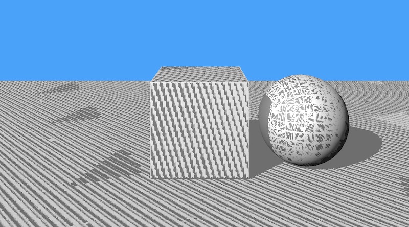
可以看到,虽然方块和球体在平面上成功投下了阴影,但是非阴影区域却也出现了许多阴影条纹。这是由于自阴影引起的阴影瑕疵(shadow acne)。
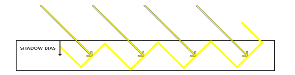
自阴影是由于Shadow Receiver阶段,像素和自身在ShadowCaster产生的ShadowMap深度进行对比,由于是同一像素,理论深度应该是一样的。但因为ShadowMap贴图本身分辨率有限,Camera视角的多个像素投影到ShadowMap上可能是同一个位置,如下图所示:
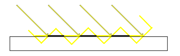
每一条斜黄线断代表ShadowMap贴图中的一个像素,对应到水平地面上可能覆盖多个像素。多个像素里有些深度较大,有些深度较小,因而产生了条状瑕疵。
解决这个问题,通常引入Bias。 而Bias又分为Depth Bias和 Normal Bias.
Normal Bias是在将像素世界坐标投影到ShadowMap之前,先将其按照法线方向做一定的偏移:
代码如下:
float3 shadowMapPos = WorldToShadowMapPos(positionWS + normalWS * _ShadowParams.y);_ShadowParams.y为normal bias数值,目前直接从Light组件中读取
深度偏移则是直接在深度比较时,对深度值加入一定的Bias数值。 代码实现如下:
//使用使用_ShadowParams.x做深度bias
#if UNITY_REVERSED_Z
    // depthToLight < depth 表示在阴影之中
    return clamp(step(depthToLight + _ShadowParams.x,depth), 0,_ShadowParams.z);
#else
    // depthToLight > depth表示在阴影之中
    return clamp(step(depth,depthToLight - _ShadowParams.x), 0,_ShadowParams.z);
#endif
其中_ShadowParams.x为depth bias的数值,也是直接取自Light组件。
修正后的效果:

到目前位置,我们已经大致在SRP中实现了平行光阴影的计算渲染。 但还存在如下问题:
- 在编辑器的SceneView中无法看到阴影.
- 如果把摄像机的far clip plane调大,阴影质量也会变得越来愈差.
- Bias的数值计算需要优化
其中1、2两点,都是由于ShadowMap的贴图精度无法满足要求而引起的。 因为摄像机视野越远,ShadowMap贴图需要覆盖的场景范围就越广,导致单位面积精度下降。 而SceneView中的摄像机,其far clip plane通常是好几万级别的,所以直接阴影就消失不见了。
为了解决这个问题,通常要使用Cascaded Shadow Mapping技术. 这会在后续实现。
而Bias的问题,目前是直接取了Light组件的设置,更好的方式是要结合ShadowMap分辨率来计算恰当的偏移。这暂且不在此文讨论范围了。