-
Notifications
You must be signed in to change notification settings - Fork 2
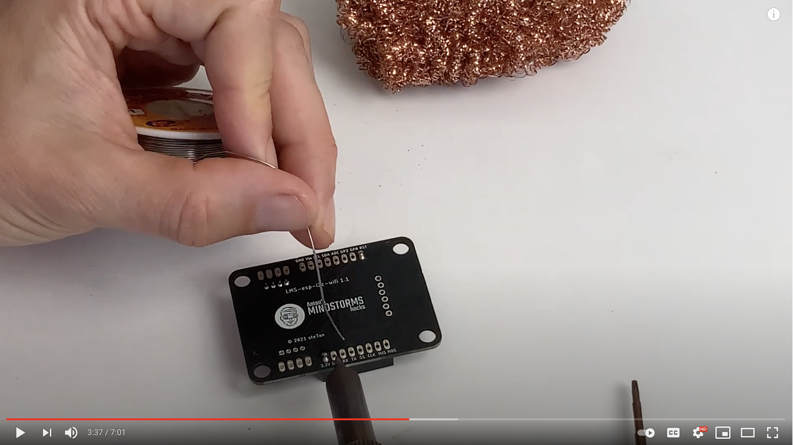
Assembling the esp board
Anton Vanhoucke edited this page Jun 25, 2021
·
2 revisions
- The 8 pin female headers go on each side of the chip.
- The grove port is best soldered on the bottom right side. (Up is when the boot and reset buttons are up, and when you can read all text.)
- The 4 pin female header goes bottom right, so it connects to the distance sensor breakout board
