Warning
KAMP aka Klipper-Adaptive-Meshing-Purging should be removed from your klipper prior to using Eddy. Please comment out the include line. ie #[include ./KAMP/adaptive_meshing.cfg] from your KAMP_SETTINGS.cfg
Instead KAMP has been integrated into klipper as of January 2024 and you should use the ADAPTIVE=1 option in your BED_MESH_CALIBRATION calls. You can find more Information on Adaptive Mesh Here
Warning
As it stands, Eddy requires the use of BTT's fork of klipper found HERE. This is included in the guide as the first step.
The pull request to merge this into mainline klipper has been made and it should be integrated shortly. Until then this is a STRICT REQUIREMENT.
- BTT Eddy Dimensions and Probe Location
- Compiling Firmware
- Printer Configuration
- Drive Current Calibration
- Mapping Eddy Readings To Nozzle Heights
- Bed Mesh Calibration
- Temperature Compensation Calibration
- Bed Mesh Calibration Parameters
- Bed Mesh Scan Height
- Bed Mesh Rapid Scanning
- FAQ - Frequently Asked Questions
- Known Issues
For a video tutorial covering many of the points below, please watch the video located here
The dimensions below will help you to understand where the center of the coil is when measuring the X and Y offsets from point 15.
Tip
When installing the Eddy (USB version), try to avoid running the cable alongside other cables that are very electrically noisy such as stepper motor cables. If you must run it alongside such cables then do your best to separate the two. Additionally, if you are handy with a crimping tool and have additional crimps, it is also a good idea to trim the cable down to the needed length by trimming the end that connects to the Eddy. This is non-essential and should only be attempted by those who are confident that they can carry the task out without error. If there is slack remaining in the cable, do not wind it in a coil, rather wind it in a figure of 8.
Tip
For detailed wiring and mounting instructions for both the Eddy and Eddy Coil, please refer to the PDF manual. This guide picks up assuming that you have completed the physical installation.
Important
Some people confuse the current calibration height of 20mm with the mounting height of 2mm. Be sure to mount the Eddy so that the base sits a maximum of 2mm above the nozzle. The 20mm height is only used when calibrating the coil current later in this guide.

Important
The firmware compilation instructions below only apply to the Eddy USB. If you are using an Eddy Coil then you will have it connected to the I2C port on a toolboard. You will need to compile firmware for that toolboard using the BIGTREETECH branch and then install it onto that toolboard. When configuring the Eddy within Klipper you will just need to specify that it communicates using the I2C port on that toolboard which will depend on the pins for that board.
After changing to the BTT specific branch of Klipper, you should update all of your device firmware such that it is compiled using this branch. This applies to motherboard and toolboards that may be connected to your system. Soon, the BTT branch will be merged with mainline klipper and at that point, you will be able to run mainline on all devices. We recommend ensuring that all other devices are updated before proceeding with this guide.
Still accurate as of 02 July 2024.
- Change to BTT klipper by entering the following via SSH
cd ~/klipper
git remote add eddy https://github.com/bigtreetech/klipper
git fetch eddy
git checkout eddy/eddy
- SSH into BIGTREETECH PI or your host device
- Type
cd ~/klipper
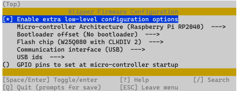
make menuconfig
- Use these settings to compile the firmware.

- Once set, hit 'Q' and when asked, select yes to save.
- Type
maketo compile. - Disconnect power to Eddy
- Push and hold boot button on Eddy (Its next to where the cable plugs in) and at the same time, plug in the cable to your BIGTREETECH Pi

- SSH into host device
- Type
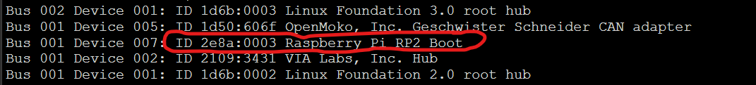
lsusbinto the command line. You should see eddy.

-
Type
cd ~/klipperinto command line -
Type
make flash FLASH_DEVICE=2e8a:0003Remember to change 2e8a:0003 to your device ID you found in step 9 -
Type
ls /dev/serial/by-id/*into the command line. The found device will be what you enter into your klipper config under [mcu eddy] for the Serial variable.[!NOTE]
-
Type into command line
sudo reboot
Important
You can use the Eddy as the z endstop or you can use another device as an endstop. If you decide to use another device as an endstop then set up your homing and endstop according to that device. If you want to enable Z-Homing/Endstop for the eddy do the following things:
-
Under your [stepper_z] in printer.cfg change
endstop_pin: PA5toendstop_pin: probe:z_virtual_endstopand comment out or removeposition_endstop: 0. Note that your current endstop may not be PA5 so just look for the line that matches your current endstop and comment it out. -
Ensure that you have the
SET_Z_FROM_PROBEandG28macro definitions from the sample configuration file included into your printer configuration file. Take note that if you are using a KNOMI then there is no need to have two instances of the G28 macro definition and you can remove the one from the KNOMI.cfg file. -
Add the rest of the contents of the sample configuration file to your printer.cfg. Please pay close attention to the guidelines and comments within the sample configuration file. They will help you to understand which macros to use/uncomment and how to calculate some of the important values for your printer. [!IMPORTANT] The sample configuration requires you to adjust the x_offset and y_offset to match your probe position relative to your nozzle. You can do that by following these steps found HERE and also by using the images at the top of this guide which show the center location of the Eddy coil. Common settings are included within the sample config file.
- Place Eddy Approx. 20mm above the bed. If you plan to use the Eddy as an endstop then you will not yet be able to home with it and you will need to manually move the gantry or bed such that the Eddy is 20mm above the bed.
- From Mainsail or Fluidd run the command
LDC_CALIBRATE_DRIVE_CURRENT CHIP=btt_eddy - Type
SAVE_CONFIGto save the drive current to your config
Now that the drive current has been calibrated, the Eddy will be able to obtain readings from the print bed. Klipper needs to know how those readings correspond to the height of the nozzle. The following calibration procedure positions the nozzle on the bed so that the z height is = 0. It then takes readings from the Eddy as it gradually increases the nozzle height so that it can map those readings to known heights. Follow the steps below to perform this essential calibration.
Tip
If you ever find that the nozzle is sitting either too high or too low when it is supposed to be at z=0 then performing this quick calibration again will likely solve your issue. There is no need to set a z-offset. Movement of the probe relative to the nozzle through maintenance may result in the need for this calibration.
Tip
Choose your own adventure! If you want to run the mapping the manual way then follow steps 22 thru 26 If you want the easy way then simply follow steps 19 thru 21
- Send the command
PROBE_EDDY_CURRENT_CALIBRATE_AUTO CHIP=btt_eddy - Follow the prompts on the klipper UI to lower the nozzle until it sandwiches a piece of paper between it and the bed but be careful not to dig into the bed. The paper should still be able to move with some force applied.
- Click accept and watch as the Eddy performs the mapping. Be sure to send
SAVE_CONFIGwhen it is done. Skip ahead to Bed Mesh Calibration.
Tip
Only perform the steps below if you did not perform steps 19 thru 21.
-
Home X and Y axes with command
G28 X Y -
Make sure you dont have a bed heightmap loaded. Send
BED_MESH_CLEARfrom the console to clear the heightmap. -
Move Nozzle to Centre of the bed with
G0 X125 Y125 F6000. The given command assumes a 250x250 printer but you will need to adjust it for your bed size. Take your bed size and divide it by 2 on X and Y and then use those values for the X and Y values in the command. -
Start the mapping by typing
PROBE_EDDY_CURRENT_CALIBRATE CHIP=btt_eddy. You will see an adjustment box that will allow you to lower the nozzle. Lower the nozzle until it sandwiches a piece of paper between it and the bed but be careful not to dig into the bed. The paper should still be able to move with some force applied. -
Once completed use
SAVE_CONFIG
Important
Before you do this, it's a good idea to perform a Quad Gantry Leveling (Voron etc)
- Home All Axes
- Use command
BED_MESH_CALIBRATE METHOD=scan SCAN_MODE=rapid - Once completed use
SAVE_CONFIG
Caution
The following steps (30-38) are for Eddy USB Only. Eddy Coil doesnt have temperature compensation so these steps should be disregarded.
- Home All Axes and move Z 5 mm above the bed by typing
G0 Z5or using the movement UI. - Set idle timeout by typing
SET_IDLE_TIMEOUT TIMEOUT=36000 - Run
PROBE_DRIFT_CALIBRATE PROBE=btt_eddy TARGET=56 STEP=4 - This will cause the UI to display the z axis adjustment box. Use the paper method mentioned here to pinch a sheet of paper between the nozzle and the bed and then accept the value.
- Turn on your heat bed to the maximum value and your nozzle to 220C.
- If you are in a room with an air-conditioner or an open window, it would be good to turn it off and/or close the window. We want the temperature of the Eddy to rise and breezes will stop that.
- As the Eddy temp rises you will automatically be asked to perform the paper pinch method at each 4C interval. Be careful not to burn yourself on the bed as the bed can get quite hot.
- Repeat the paper test method until the calibration completes. If you find that the temperature of the Eddy is no longer increasing then you can end the calibration early using the relevant command below.
[!NOTE] By default the calibration procedure will request a manual probe every 4C between samples until the TARGET is reached.
The following additional gcode commands are available during drift calibration.
PROBE_DRIFT_NEXTmay be used to force a new sample before the step delta has been reached.PROBE_DRIFT_COMPLETEmay be used to complete calibration before the TARGET has been reached.ABORTmay be used to end calibration and discard results.
Tip
The Eddy thermal calibration process not only accounts for Eddy probe drift but it also accounts for thermal expansion of the mechanical components within your machine. This expansion can be very significant and it can result in poor first layers when using other probes. It is important to keep in mind that if you perform the thermal calibration with the nozzle and the heated bed turned on then there will be thermal expansion from both the hotend and the heated bed. Therefore, if you later try to perform a paper test and only have either the nozzle or the heated bed turned on you may find that there is about a 0.05 gap (not enough to cause a first layer issue but enough to feel less of a pinch on the paper). If this all sounds a bit confusing then don't worry. All you need to know is that you should perform the calibration with the bed and the nozzle both hot and then subsequently print with the bed and the nozzle both hot and you will get fantastic first layers.
- Youre all done and your Eddy will now give you a beautiful first layer across a wide temperature range! :)
The Eddy allows you to perform a very rapid bed mesh scan before each print to ensure that you get the best first layer possible. To do this, we recommend replacing the standard BED_MESH_CALIBRATE macro with our modified version from the sample configuration file and then including a BED_MESH_CALIBRATE call in your print start macro.
To find out more about the parameters used in the bed mesh scan you can read the Klipper documentation here: Bed Mesh Calibration
The scan height is set by the horizontal_move_z option in [bed_mesh]. In
addition it can be supplied with the BED_MESH_CALIBRATE gcode command via the
HORIZONTAL_MOVE_Z parameter.
The scan height must be sufficiently low to avoid scanning errors. Typically
a height of 2mm (ie: HORIZONTAL_MOVE_Z=2) should work well, presuming that the
probe is mounted correctly.
It should be noted that if the probe is more than 4mm above the surface then the results will be invalid. Thus, scanning is not possible on beds with severe surface deviation or beds with extreme tilt that hasn't been corrected.
When performing a rapid bed mesh scan there is little time to accumulate many samples per point so that they can be averaged and have noise removed. Therefore a rapid scan may not be as accurate as a standard bed mesh scan but in most cases it will still produce a fine first layer.
Rapid scans can be improved by allowing the travel planner to slightly overshoot the scanned bed mesh and smooth the moves. You can configure this overshoot in the bed_mesh configuration section using the scan_overshoot: parameter. Note that you will need to ensure that the axis can travel to the mesh boundary plus this overshoot value on your printer so be careful not to specify a value that is too high. Usually 8mm is plenty.
- This will happen when you try to execute two successive
PROBEcommands. Always raise the gantry by a few mm betweenPROBEcommands to avoid this.
- Make sure you are using the correct macro call.
BED_MESH_CALIBRATE SCAN_MODE=rapid METHOD=scan - Remove or alter KAMP - Adaptive Bed Mesh and any custom BED_MESH_CALIBRATE macros. Use klipper adaptive mesh instead or alternatively do not include KAMP/Adaptive_Meshing.cfg in your KAMP_Settings.cfg Information on Adaptive Mesh Here
- It depends on your needs. Eddy USB and Eddy Coil are nearly identical, however Eddy Coil is more for toolhead boards and connects via I2C connectors.
- Eddy Coil does not have temperature compensation and so it may be less reliable for homing if you are using it within a sealed chamber..
- Coming from a standard probe, this may seem like a bug. However if you have calibrated the Eddy correctly and are using the special homing macros, then there will be no need for a z-offset. Explaining why is a bit long winded but essentially when it comes to an Eddy, the z-offset parameter does not adjust the height at which the nozzle prints, it just adjusts the height at which homing or probing triggers. If you have a mind that enjoys understanding things at a deeper level then here is a writeup to give you something to chew on: Z-Offsets with Eddy Current Probes
- While we strongly recommend simply performing the Eddy probe calibration in order to get a nozzle height that is just right, you can still simulate a standard z-offset by uncommenting certain macros in the sample configuration file. Simply uncomment any macro that is related to the beta z-offset functionality and you will be able to use the standard mainsail buttons to raise/lower then nozzle and save that height as a z-offset.
-
BTT Knomi will cause z-hops during a scan. If you are using the Eddy as an endstop then simply comment out the G28 macro in KNOMI.CFG and use the macro from the sample Eddy config. If you are using another device as an endstop then modify your G28 macro in the KNOMI.cfg, specifically this line.
SET_GCODE_VARIABLE MACRO=_KNOMI_STATUS VARIABLE=probing VALUE=True
BTT_BED_MESH_CALIBRATE
SET_GCODE_VARIABLE MACRO=_KNOMI_STATUS VARIABLE=probing VALUE=False
so that it looks like this
SET_GCODE_VARIABLE MACRO=_KNOMI_STATUS VARIABLE=probing VALUE=True
BTT_BED_MESH_CALIBRATE SCAN_MODE=rapid METHOD=scan
SET_GCODE_VARIABLE MACRO=_KNOMI_STATUS VARIABLE=probing VALUE=False