-
Notifications
You must be signed in to change notification settings - Fork 22
hardware
Mariano Alvira edited this page Jan 29, 2013
·
11 revisions
This is the MC13224v Hardware Guide. The purpose of this page is to catalog and document all the known available hardware based on the MC13224.
###Redwire
- M12: $38. FCC approved module designed for low power and OTA reprogramming. Buck, 32kHz crystal, external bootflash included.
- Econotag: ~$55. inexpensive stand-alone dev. kit. Easy JTAG debugging. No extra programming hardware needed. Open Hardware released under CC-BY-SA.
- Redbee Module: ~$45. connector-ized module. DISCONTINUED
- Redbee Dev: ~$55. simple development board for the Redbee Module. DISCONTINUED
- QuahogCon 2010 Badge: Econotag with batteries. Open Hardware released under CC-BY-SA.
###CEL
- FreeStar Pro: ~$35. FCC approved module. Has PA. Needs to be soldered to an application board.
###Freescale
- 1322x-SRB (Sensor Reference Board): ~$540. Many different sensors, lights, and pushbuttons.
- 1322x-NCB (Network Coordinator Board): ~-$160. (yes, negative, see below) Sensor Reference Board with Graphic LCD.
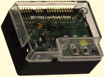
- 1322x-LPN (Low Power Node): ~$120. Sensor board but without the sensor --- and trimmed down a bit.
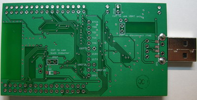
- 1322x-USB (USB dongle and 802.15.4/ZigBee packet sniffer): ~$80. Bare bones MC13224v and FT232 UART in a small case.
###Nivis
- VersaNode: : price unknown. FCC approved module. Has PA. Needs to be soldered to an application board.
####MC13224 details:
- Power: USB regulated to 3v29 (short JP11 to regulate to 3v55); up to 16V in on JP13; VBATT available on JP12.
- JTAG: on-board FT2232H --- interface A
- NEXUS: No.
- UART1: on-board FT2232H --- interface B
- VREF2: connected to FT2232H pins. Available on JP15 and JP16. Additional pads available to make VREF2 erases easy. (Short JP15 and JP16).
- RESET: Push button, FT2232H, or through-hole.
- Antenna: PCB inverted-F
- Power Amplifier: None.
- LNA: None.
- 32kHz: Optional. Pads available on JP26, C9 and C10.
- Buck inductor: Optional. Cut JP27 on back of board. Populate L1. Populate D2 on the back.
- FCC ID: No.
####Other features:
- Red LED, Q3 on TX_ON (can be used to indicate either TX or RX)
- Green LED, Q4 on RX_ON (can be used to indicate either TX or RX)
- Two push buttons: S1 (between KBI0 and 4); and S2 (between KBI1 and 5)
- Stand-alone operation: no extra programming hardware is necessary.
####Documentation:
###Redbee Module _DISCONTINUED_####MC13224 details:
- Power: VBAT available on underside connector.
- JTAG JTAG pads available on JP2.
- NEXUS No.
- UART1 available on underside connector.
- VREF2 Can be toggled via DIP switch S2
- RESET Push button, JTAG pads, or underside connector.
- Antenna PCB inverted-F
- Power Amplifier: None.
- LNA: None.
- 32kHz: Yes.
- Buck inductor: Optional. Remove R5. Populate L1 on underside.
- FCC ID: No.
- Red LED, Q2 on TX_ON (can be used to indicate either TX or RX)
- Module with connector.
- Accepts Redbee Module.
- Powers module from USB.
- FT232 connects to UART1.
- RGB LED Q2
- Five push buttons: short to GND.
- AT45 serial dataflash
- Potentiometer
- 1v8 reference
- Temperature sensor
- 2kHz Buzzer
- 50-pin breakout
- Power: USB regulated to 3v29 (short JP11 to regulate to 3v55); up to 16V in on JP13; VBAT available on JP12; 2xAAA battery holders connected in series to VBAT.
- JTAG: on-board FT2232H --- interface A
- NEXUS: No.
- UART1: on-board FT2232H --- interface B
- VREF2: connected to FT2232H pins. Available on JP15 and JP16. Additional pads available to make VREF2 erases easy. (Short JP15 and JP16).
- RESET: Push button, FT2232H, or through-hole.
- Antenna: PCB inverted-F
- Power Amplifier: None.
- LNA: None.
- 32kHz: Optional. Pads available on JP26, C9 and C10.
- Buck inductor: Optional. Cut JP27 on back of board. Populate L1. Populate D2 on the back.
- FCC ID: No.
- Red LED, Q3 on TX_ON (can be used to indicate either TX or RX)
- Green LED, Q4 on RX_ON (can be used to indicate either TX or RX)
- 5x Red LEDs on bottom left corner
- Red, Yellow and Green LEDs on bottom right.
- Two push buttons: S1 (between KBI0 and 4); and S2 (between KBI1 and 5)
- Stand-alone operation: no extra programming hardware is necessary.
- Doc package --- schematic, gerber, and BOM released under CC-BY-SA.
- Power: VBAT pin
- JTAG: pads available.
- NEXUS: No.
- UART1: pads available.
- VREF2: pads available.
- RESET: pad available.
- Antenna: PCB inverted-F (ZFSM-201-1) or MMCX connector (ZFSM-201-1C)
- Power Amplifier: Yes. +20dBm max. (193mA)
- LNA: None.
- 32kHz: Yes.
- Buck inductor: pads available.
- FCC ID: Yes.
See the Freestar Pro product page for full documentaion.
Freescale only sells the USB board individually, the rest are available in bundles. From http://www.freescale.com/webapp/sps/site/prod_summary.jsp?code=1322x_Dev_Kits&fsrch=1:
- 1322XEVK  : 4S + 3N + 2L + U = $2000
- 1322XNSK-DBG: S + N + L + U = $ 580
- 1322XDSK-DBG: S + N = $ 380
- 1322XUSB  : U = $ 80
If you solve this system on equations (4 equations and 4 unknowns), then you get:
- S = $ 540
- N = $ -160
- L = $ 120
- U = $ 80
Freescale Sensor Reference Board: buy now from Freescale
- Power: USB or DC Jack (12V Max) or 2x AA batteries
- JTAG: 20-pin 0.1'' header
- NEXUS: No.
- UART1: FT232.
- VREF2: Toggle with Jumpers.
- RESET: JTAG and push button.
- Antenna: PCB inverted-F
- Power Amplifier: None.
- LNA: None.
- 32kHz: Optional.
- Buck inductor: No.
- FCC ID: No.
- Audio: input and output
- Pressure sensor
- Temp. Sensor
- 3 axis accelerometer
- Joysick
- Power LED
- 4 push buttons
- 4 GPIO LEDs.
- On/Off switch
- Power: USB or DC Jack (12V Max) or 2x AA batteries
- JTAG: 20-pin 0.1'' header
- NEXUS: Yes.
- UART1: FT232.
- VREF2: Toggle with Jumpers.
- RESET: JTAG and push button.
- Antenna: External SMA antenna or PCB inverted-F
- Power Amplifier: None.
- LNA: None.
- 32kHz: Optional.
- Buck inductor: No.
- FCC ID: No.
- 128x64 LCD with LED backlight
- Audio: input and output
- Pressure sensor
- Temp. Sensor
- 3 axis accelerometer
- Joysick
- Power LED
- 4 push buttons
- 4 GPIO LEDs.
- On/Off switch
- Power: DC Jack (12V Max), or 2x AAA batteries, or optionally coin-cell (pads for CR2450 or CR2477 provided)
- JTAG: 20-pin 0.1'' header
- NEXUS: No.
- UART1: On pin header.
- VREF2: Toggle with Jumpers.
- RESET: JTAG and push button.
- Antenna: PCB inverted-F.
- Power Amplifier: None.
- LNA: None.
- 32kHz: Yes.
- Buck inductor: Optional.
- FCC ID: No.
- PFET to switch off peripherals
- 1v5 voltage reference
- Power LED
- 2 push buttons
- 2 GPIO LEDs.
- On/Off Switch
- Power: USB
- JTAG: pads for 20-pin 0.1'' header (you have to remove the PCB from the casing)
- NEXUS: No.
- UART1: FT232.
- VREF2: Pads for jumpers.
- RESET: JTAG and push button.
- Antenna: SMD ceramic.
- Power Amplifier: None.
- LNA: None.
- 32kHz: No.
- Buck inductor: No.
- FCC ID: No.
- Power LED
- 2 push buttons
- 1 GPIO LEDs.
- Power: VBAT pin
- JTAG: pads available.
- NEXUS: No.
- UART1: pads available.
- VREF2: pads available.
- RESET: pad available.
- Antenna: MMCX connector
- Power Amplifier: Yes. +12dBm max. (57mA)
- LNA: None.
- 32kHz: Yes.
- Buck inductor: No.
- FCC ID: Yes.
VersaNode datasheet
© 2013 Mariano Alvira. Distributed under the GNU FDL v1.3 <script type="text/javascript"> var _gaq = _gaq || []; _gaq.push(['_setAccount', 'UA-9770084-1']); _gaq.push(['_trackPageview']); (function() { var ga = document.createElement('script'); ga.type = 'text/javascript'; ga.async = true; ga.src = ('https:' == document.location.protocol ? 'https://ssl' : 'http://www') + '.google-analytics.com/ga.js'; var s = document.getElementsByTagName('script')[0]; s.parentNode.insertBefore(ga, s); })(); </script>


