-
Notifications
You must be signed in to change notification settings - Fork 37
Basics of GLSL in Possumwood
This tutorial introduces basic concepts of OpenGL drawing in Possumwood.
The OpenGL rendering implementation closely mirrors the OpenGL 4 API concepts of a VBO, vertex shader, fragment shader and a program object, while translating them to a node graph. The basic nodes are draw node executing the rendering, vertex shader and fragment shader nodes implementing shader compilation, the program node performing linking and finally a vertex data source, in our case a source converting a polymesh instance.
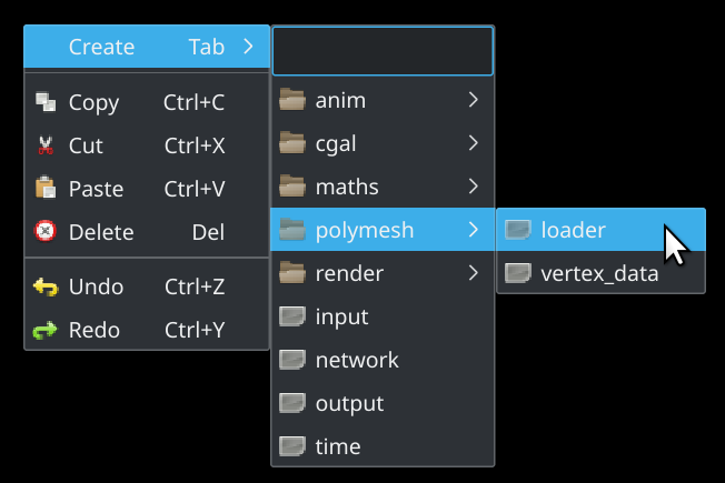
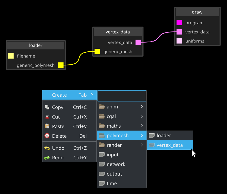
We will use the polymesh plugin to load an .obj mesh file. Just right-click in the node editor and create a new polymesh loader.
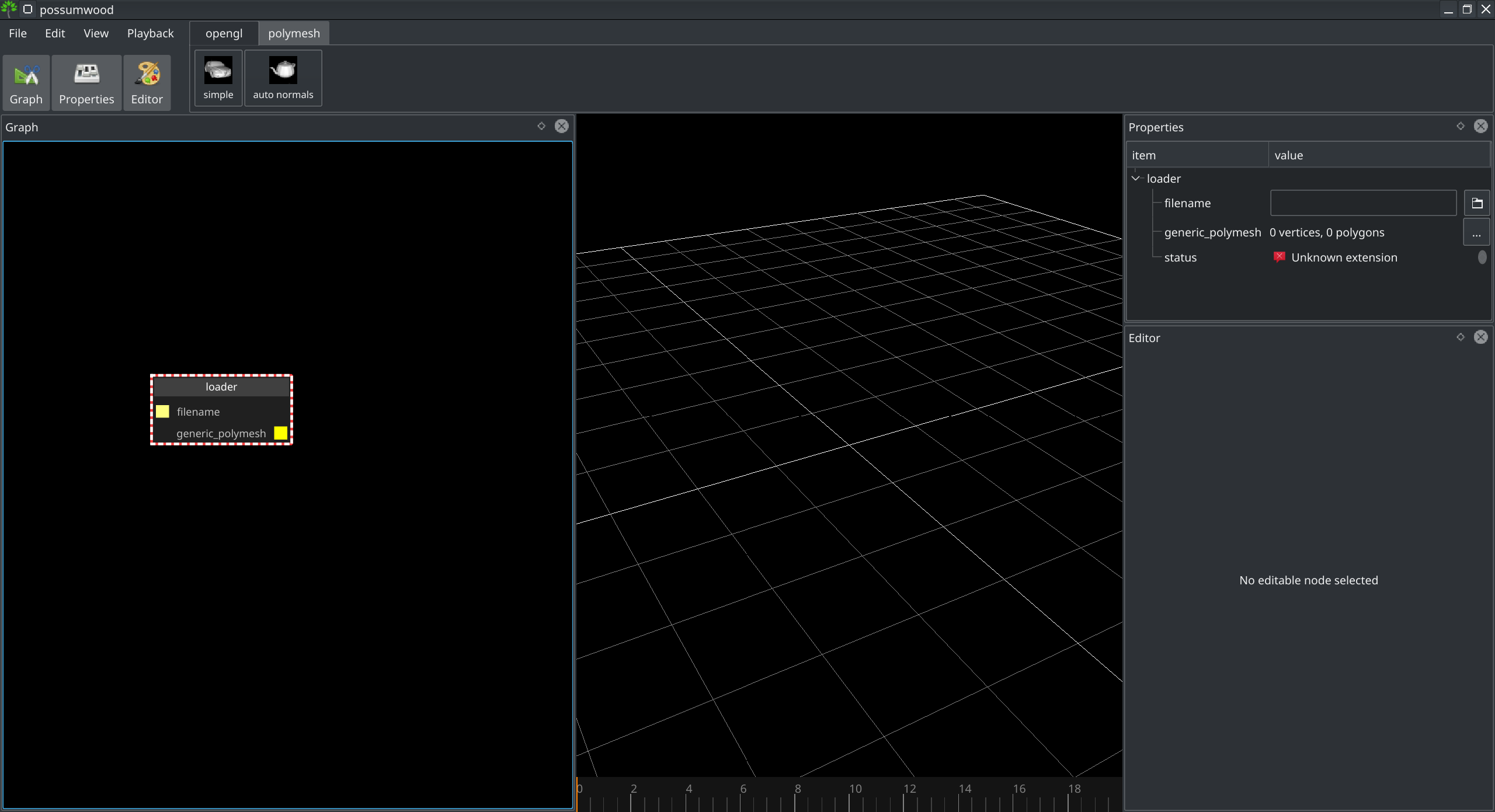
After creation, you can see on the right hand side a number of properties of the newly created node.
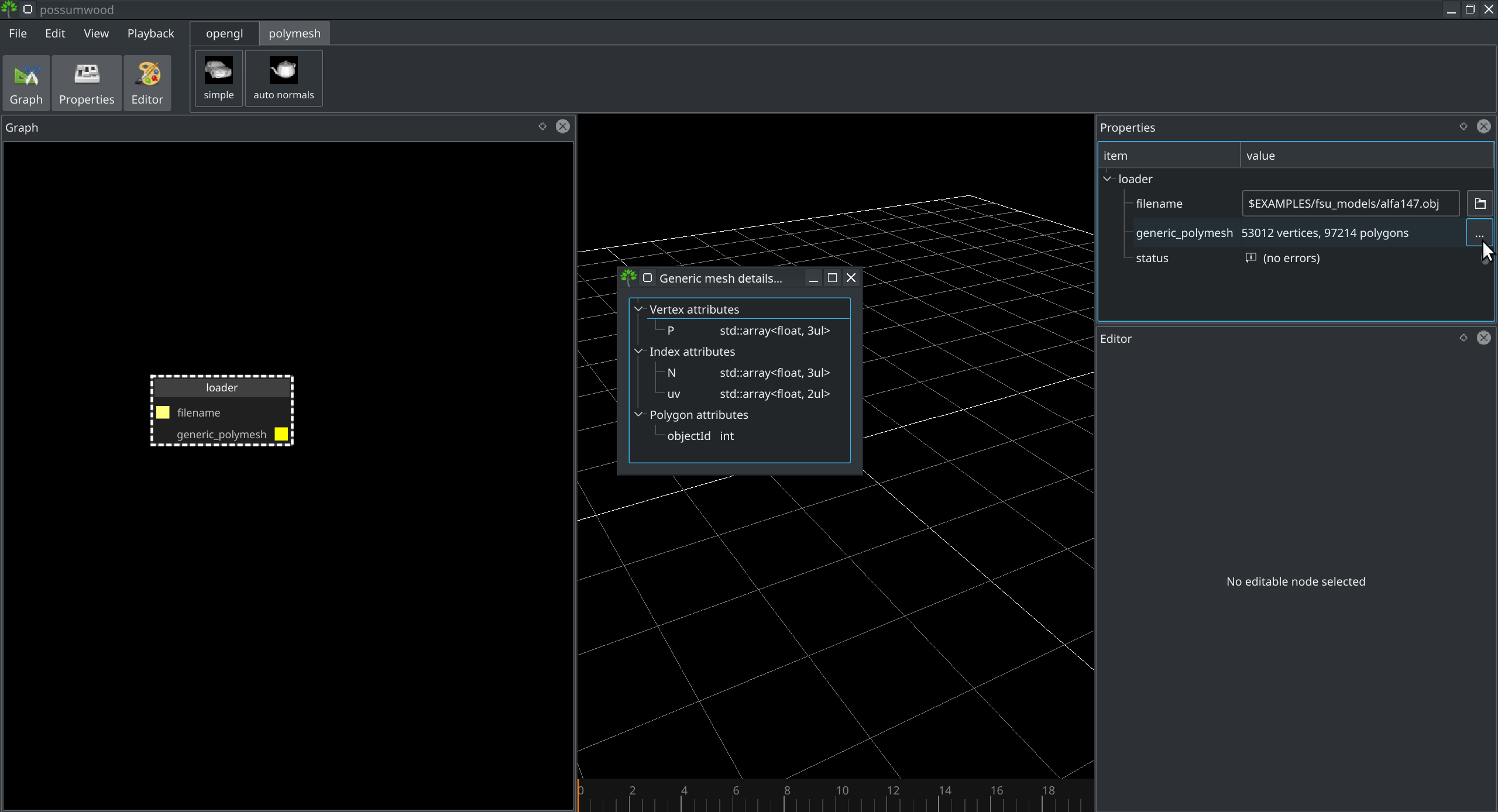
By clicking the browse icon next to the filename, you can go and select a mesh to load. In this tutorial, we will use the fsu_models/alfa147.obj from examples directory.
After loading mesh, you will notice that the generic polymesh now contains 53k vertices, 97k polygons, and by clicking on the "..." details icon, you can see we've loaded P vertex attribute, N and uv varying attributes and objectId polygon attribute.
At the core of the OpenGL drawing in Possumwood is the render/draw node. This node has 3 parameters - program, vertex data and uniforms.
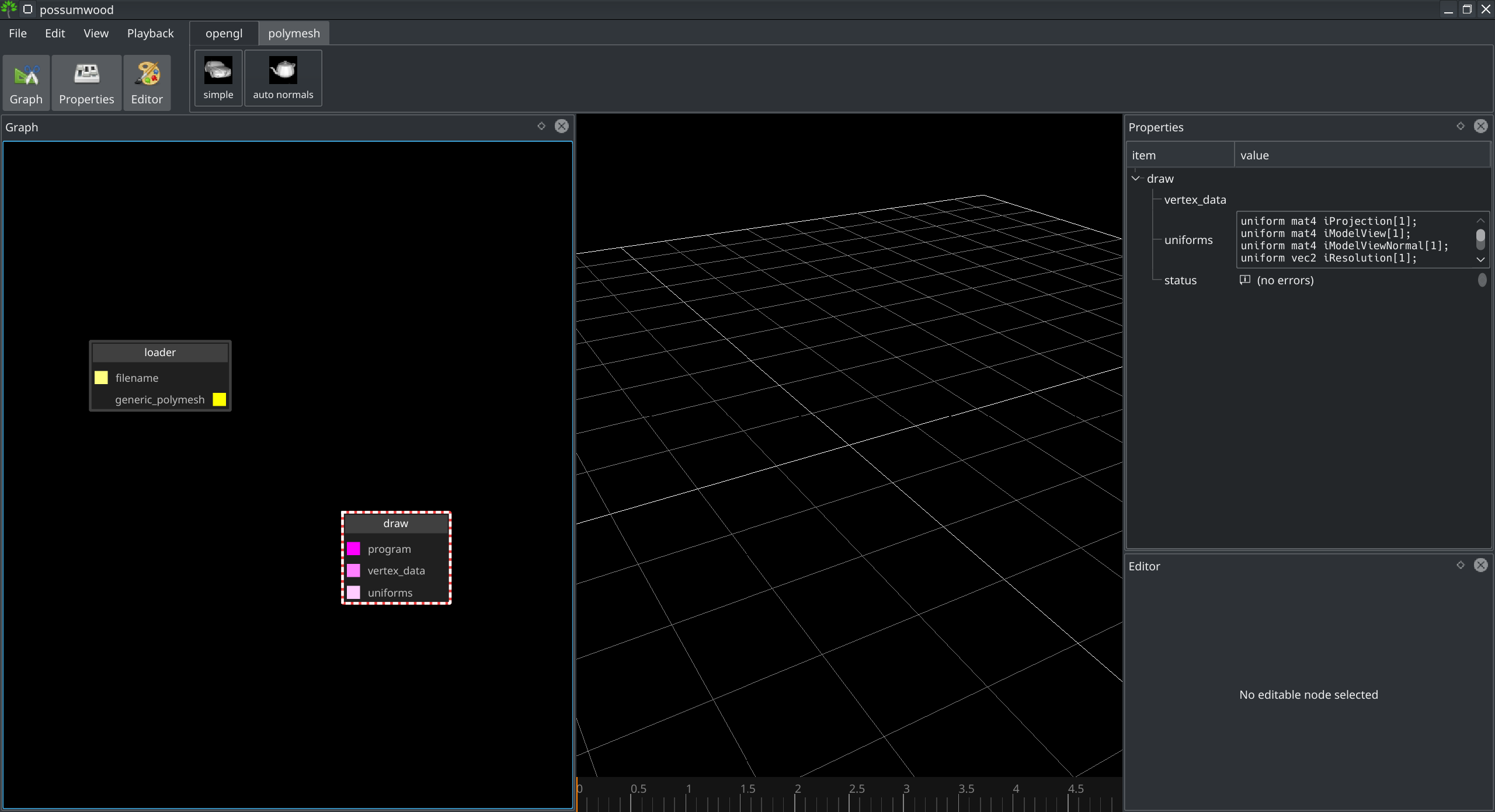
The uniforms parameter has a default value that allows the OpenGL shaders to access viewport data. To begin with, we don't need anything else - we will not alter this parameter or connect anything else to this input.
The vertex data parameter needs to be connected to a vertex data source - a specific node that converts its inputs into a set of VBOs. In our case, we need to convert a generic polymesh object using the polymesh/vertex_data node.
Because the program parameter has a default value as well, just by connecting the vertex data attribute, you can see the a car in the viewport.
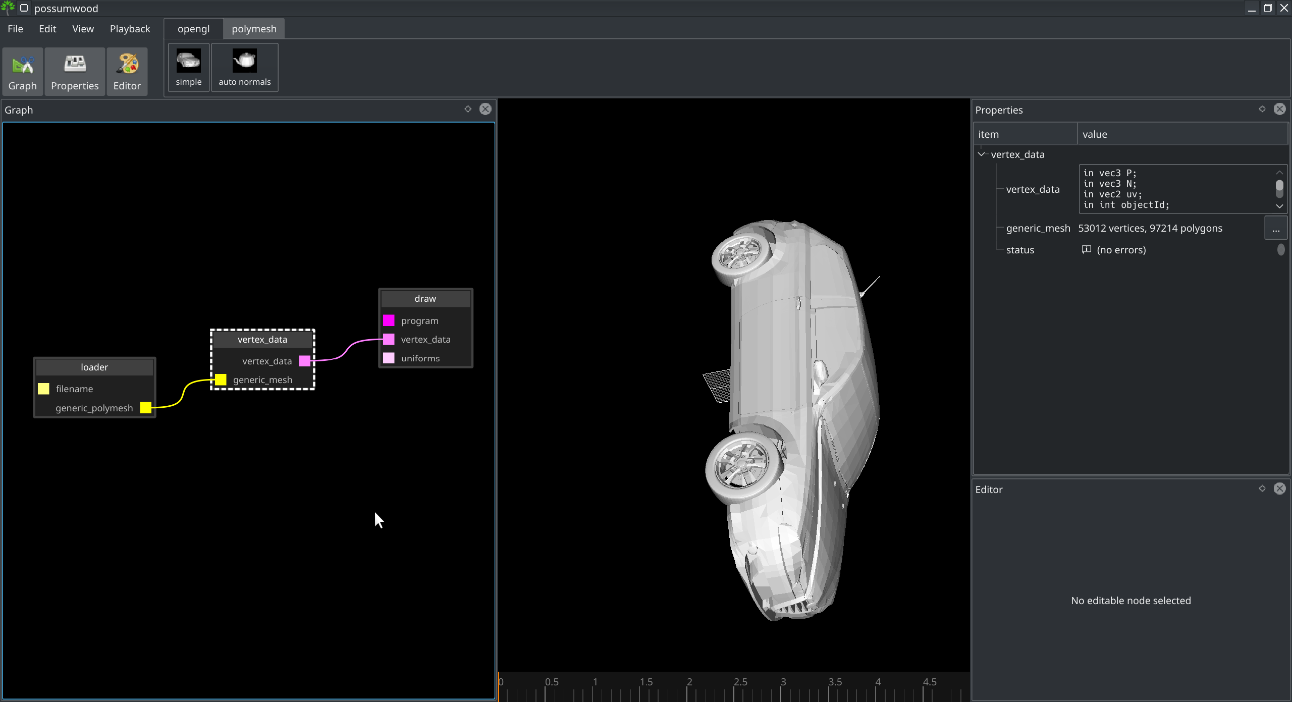
In the properties of the vertex data node, you can see that all properties of the original polymesh instance have been converted to vertex data attributes. The default implementation of the shaders does not make use of most of these - it will only tap into the P parameter to get the positional information of each vertex.
The default program already provides a good starting point for displaying an object in the viewport. It provides a simple flat shader, with normals derived from polygon differentials (i.e., "flat" normals) and a very simple shading model.
To allow for editing the GLSL code, we need to replace the default program with a network of editable nodes. Currently, an OpenGL program in Possumwood consists of a program node, with a connection to a fragment_shader and a vertex_shader.
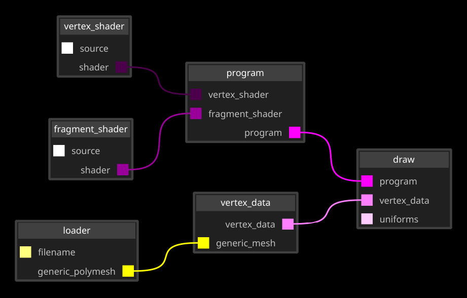
Selecting any of the shader nodes with the editor panel open allows to change the source code of each shader. The compilation is run immediately after each press of the "apply" button.
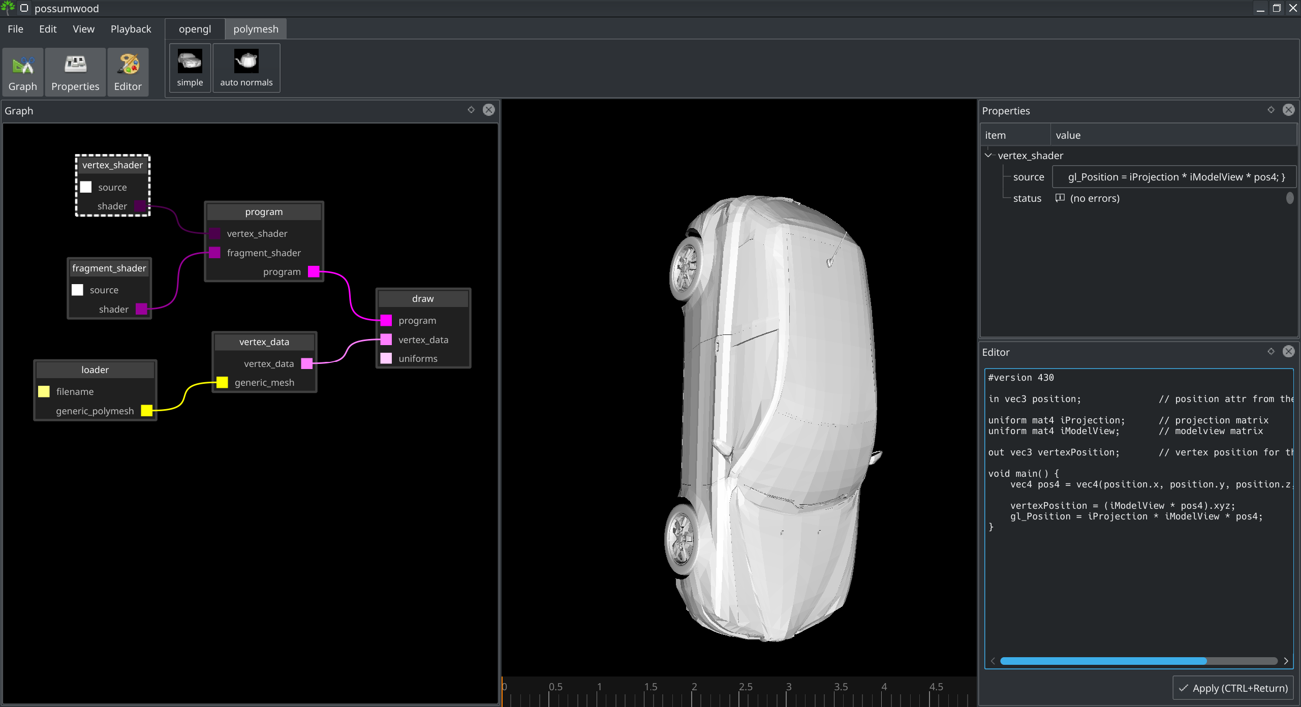
The default vertex shader simply passes through the position attribute to the fragment shader, after applying projection and modelview transformations. For the vertexPosition value, we are interested in vertices in world space - inly modelview matrix is applied.
#version 430

in vec3 P;                     // position attr from the vbo

uniform mat4 iProjection;      // projection matrix
uniform mat4 iModelView;       // modelview matrix

out vec3 vertexPosition;       // vertex position for the fragment shader

void main() {
	vec4 pos4 = vec4(P.x, P.y, P.z, 1);

	vertexPosition = (iModelView * pos4).xyz;
   	gl_Position = iProjection * iModelView * pos4;
}
The P attribute comes from the vertex data buffer, which in turn is passed from the vertex_data node - all data passed from the polymesh/loader node can be accessed in this way. The uniforms are part of the set of attributes accessible in the draw node by default. To see all vertex data loaded from the mesh and accessible uniform attributes, just select the draw node.
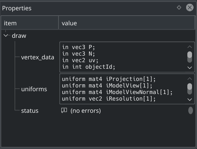
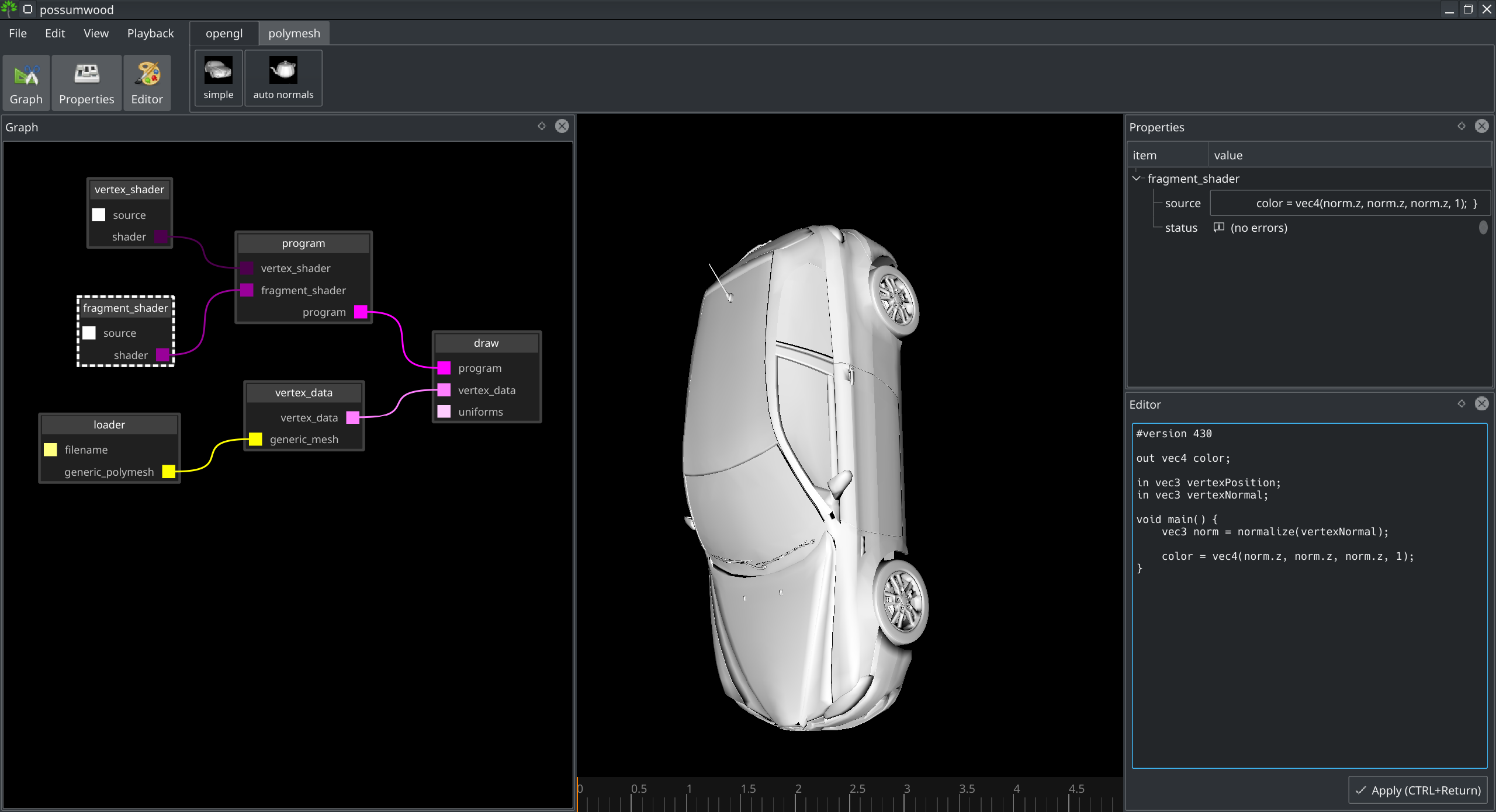
The model we are using as our example also includes the N attribute, representing the surface normals. Our current setup synthesizes flat per-polygon normals - let's use the N attribute to show normals read from the file.
To do that, we need to send the explicit vertex normal N to the fragment shader, transformed using the normal modelview matrix, which actually simplifies the shader code:
#version 430

in vec3 P;                     // position attr from the vbo
in vec3 N;                     // normal attr from the vbo

uniform mat4 iProjection;      // projection matrix
uniform mat4 iModelView;       // modelview matrix
uniform mat4 iModelViewNormal; // normal modelview matrix

out vec3 vertexPosition;       // vertex position for the fragment shader
out vec3 vertexNormal;         // vertex normal for the fragment shader

void main() {
	vec4 pos4 = vec4(P.x, P.y, P.z, 1);
	vec4 norm4 = vec4(N.x, N.y, N.z, 0);

	vertexPosition = (iModelView * pos4).xyz;
	vertexNormal = (iModelViewNormal * norm4).xyz;

   	gl_Position = iProjection * iModelView * pos4;
}
The default fragment shader relies only on the vertexPosition attribute to be passed from the vertex shader. It then uses dFdx() and dFdy() to compute X and Y differentials per-pixel, and synthesize a normal vector using cross product.
The synthesized normal vector is then used to create a simple shading by converting its Z axis to a color. This leads to a simple grey material - the surfaces parallel to the camera plane will be white, with a gradient as the surface normal edges away from the camera view direction.
#version 430

out vec4 color;

in vec3 vertexPosition;

void main() {
	vec3 dx = dFdx(vertexPosition);
	vec3 dy = dFdy(vertexPosition);

	vec3 norm = normalize(cross(dx, dy));

	color = vec4(norm.z, norm.z, norm.z, 1);
}
To use the N attribute directly, we only need to use the vertexNormal input variable (passed from the vertex shader) instead of the computation described above.
#version 430

out vec4 color;

in vec3 vertexPosition;
in vec3 vertexNormal;

void main() {
	vec3 norm = normalize(vertexNormal);

	color = vec4(norm.z, norm.z, norm.z, 1);
}
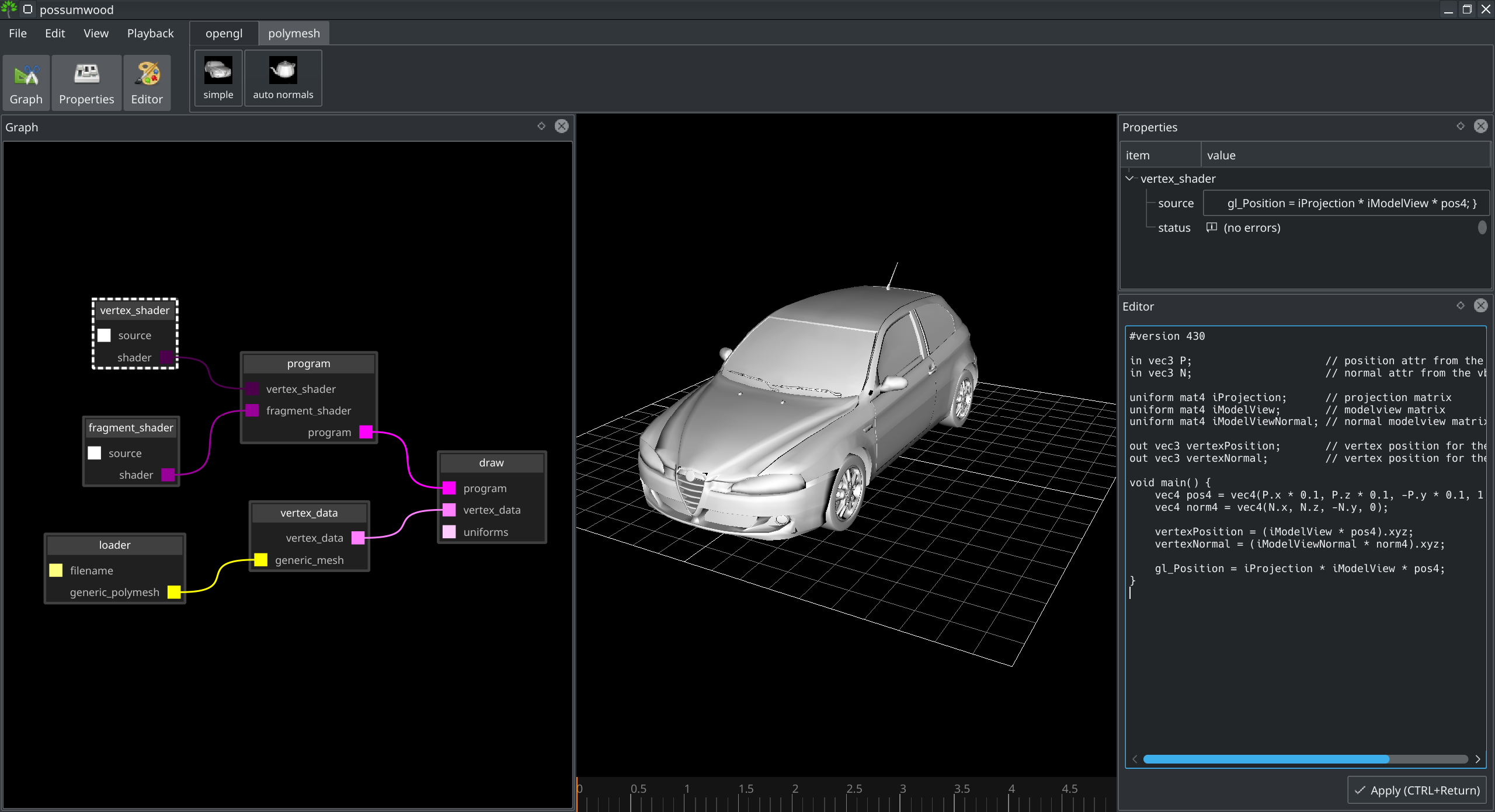
The control over the vertex shader also allows for transforming the geometry for display. For example, we can easily scale the car model to 0.1 of its original size, and rotate it so it is displayed correctly in the viewport by switching the Y and Z axis.
#version 430

in vec3 P;                     // position attr from the vbo
in vec3 N;                     // normal attr from the vbo

uniform mat4 iProjection;      // projection matrix
uniform mat4 iModelView;       // modelview matrix
uniform mat4 iModelViewNormal; // normal modelview matrix

out vec3 vertexPosition;       // vertex position for the fragment shader
out vec3 vertexNormal;         // vertex position for the fragment shader

void main() {
	vec4 pos4 = vec4(P.x * 0.1, P.z * 0.1, -P.y * 0.1, 1);
	vec4 norm4 = vec4(N.x, N.z, -N.y, 0);

	vertexPosition = (iModelView * pos4).xyz;
	vertexNormal = (iModelViewNormal * norm4).xyz;

   	gl_Position = iProjection * iModelView * pos4;
}
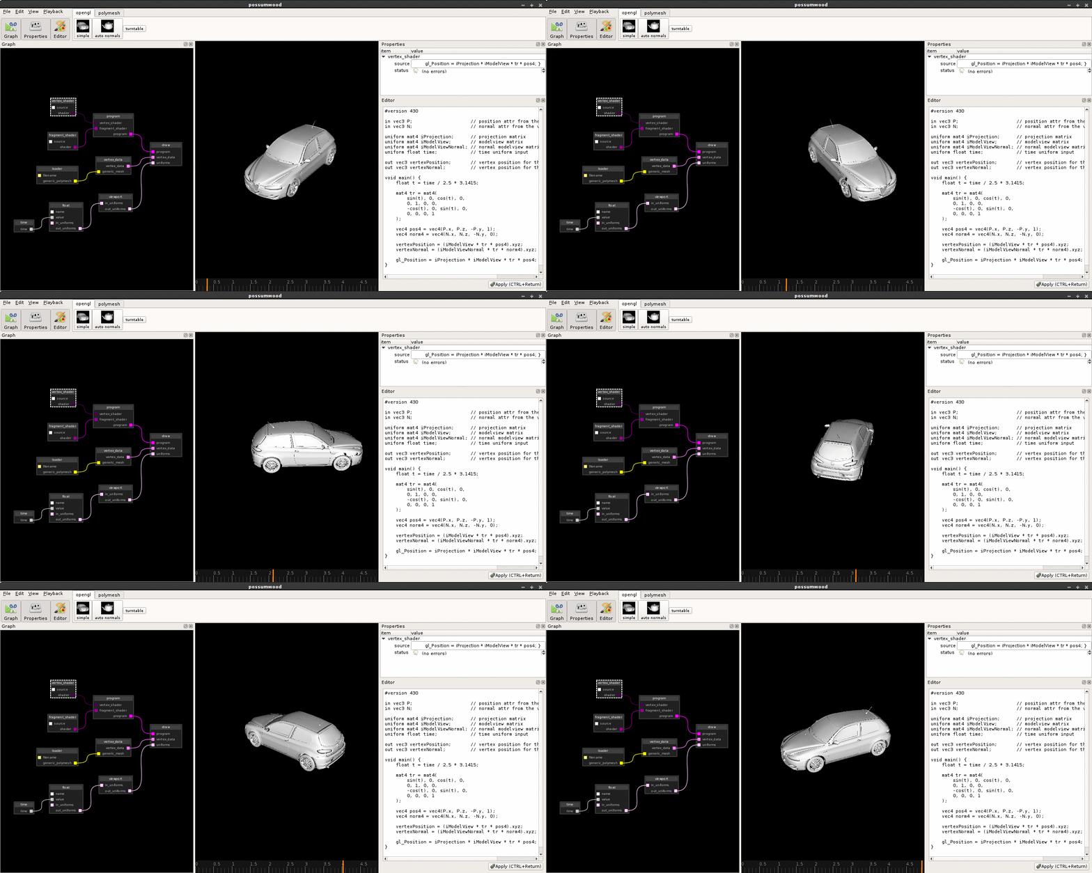
We can also use the vertex shader transformations to create a simple turntable. For this, we need to add an additional uniform to the uniforms input of the draw node.
In Possumwood, uniform nodes can be chained together to provide a composite of all uniforms used by a drawing node. We will need to get the output of the time node (a special node with a single output returning the time value from the timeline as a float parameter), feed it to a render/uniforms/float node instance, and chain the result with render/uniforms/viewport to provide access to the viewport matrices (previously included in the default uniforms value).
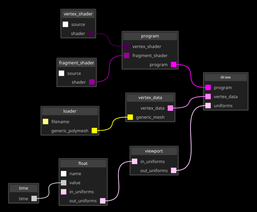
Using the new time uniform, we can generate a new transformation matrix in the vertex shader, and use it to transform the normal and vertex position before rendering.
#version 430

in vec3 P;                     // position attr from the vbo
in vec3 N;                     // normal attr from the vbo

uniform mat4 iProjection;      // projection matrix
uniform mat4 iModelView;       // modelview matrix
uniform mat4 iModelViewNormal; // normal modelview matrix
uniform float time;            // time uniform input

out vec3 vertexPosition;       // vertex position for the fragment shader
out vec3 vertexNormal;         // vertex position for the fragment shader

void main() {
	/// 360-degree rotation in 5 seconds of time
	float t = time / 2.5 * 3.1415;

	// rotation transformation along the Y axis
	mat4 tr = mat4(
		sin(t), 0, cos(t), 0,
		0, 1, 0, 0,
		-cos(t), 0, sin(t), 0,
		0, 0, 0, 1
	);

	vec4 pos4 = vec4(P.x, P.z, -P.y, 1);
	vec4 norm4 = vec4(N.x, N.z, -N.y, 0);

	vertexPosition = (iModelView * tr * pos4).xyz;
	vertexNormal = (iModelViewNormal * tr * norm4).xyz;

   	gl_Position = iProjection * iModelView * tr * pos4;
}
This leads us to the final output - a simple turntable of a car, rendered using OpenGL and shaded using OpenGL4 shaders.
Possumwood is an open source project - please contribute!