-
Notifications
You must be signed in to change notification settings - Fork 1
Wemos D1 Mini and BME280 Temperature, Humidity and Pressure Sensor


"BME280 sensor, an environmental sensor with temperature, barometric pressure and humidity" See BME280 Temperature, Humidity and Pressure Sensor for more information.
Note: before the BME280 can be used with Tasmota, make sure it's enabled. To enable it, remove the forward slashes before this line before you compile and upload tasmota to your Wemos device.
#define USE_BMP // Add I2C code for BMP085/BMP180/BMP280/BME280 sensor (+4k code)
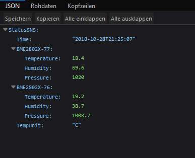
Since 2018-10-29 v6.1.2.20 you can use multiple BMP Sensors (9d981d8)
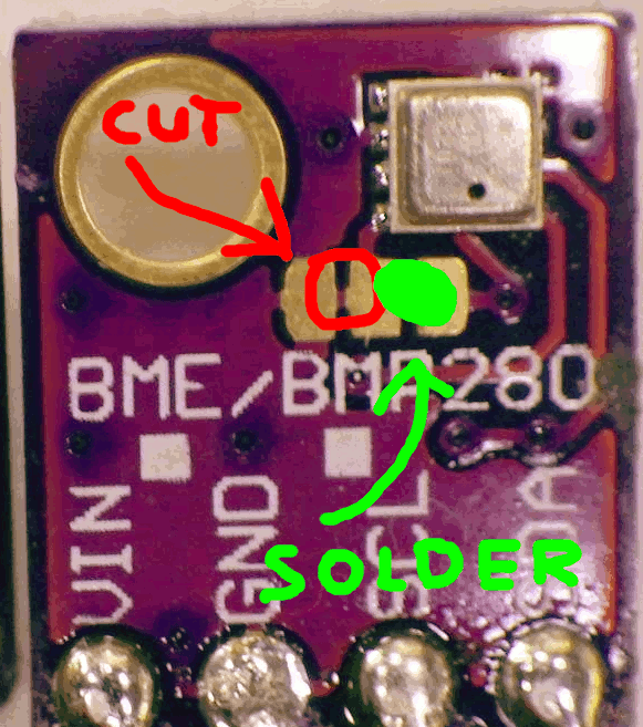
Limit is 2 BMP Sensors and you HAVE TO change the address of one sensor.
Than connect your Sensor SCL and SDA parallel to the device.
BME280 address change example:

| Wemos | BME280 |
|---|---|
| GND | GND |
| 3.3V | VCC |
| D3 (gpio0) | SDA |
| D4 (gpio2) | SCL |
If you are using breakout boards which break out pins CSB please ensure that you connect this pin to VCC to ensure that the chip stays in I2C mode - This is due to some manufacturers of breakout boards add pull-up resistors to allow for SPI compatibility (some would default to SPI, others to I2C)
Also connect the SDO pin to GND or VCC to ensure required I2C address is used by the chip - Again some manufacturers add resistors to provide external bias but due to them wanting to retain SPI compatibility such pulldown resistors may not be sufficient to ensure that the pin levels are at the correct transition during power-up / reset state.
Since the chip supports both SPI and I2C, but in Tasmota only I2C is supported you want to make sure that the chip is in I2C mode during reset/power-on and remain in that state during operation otherwise unexpected behaviour may result when the Tasmota firmware polls the chip for sensor data.
In the Configuration -> Configure Module page, select the following:
- Module Type : 18 Generic
- D3 GPIO0 : 06 I2C SDA
- D4 GPIO2 : 05 I2C SCL

After reboot of the device the displays temperature, humidity and pressure measured by the BME280.


Home | Wiki | What's new | Tutorials | FAQ | Troubleshooting | Button usage | Commands | Rules
Home
Theo's Tasmota Tips
What's New
Getting Started
Upload tools
- SonOTA
- OTA over SCP
- Esptool
- Arduino IDE
- PlatformIO
- PlatformIO CLI
- Visual Studio Code
- Python HTTP OTA server
- Node Red OTA server and firmware manager
Usage
- Button Functionality
- MQTT Features
- Supported Commands
- Using Rules
- Sensor Configuration
- PowerOnState Configuration
- SwitchMode/SwitchTopic
- Button Multipress
- Energy Saving
- KNX Features
- Misc. Tips
Devices - Additional Info
- Sonoff Basic
- Sonoff SV
- Sonoff S20 Smart Socket
- Sonoff S26 Smart Socket
- Sonoff Dual / Dual R2
- Sonoff 4CH / 4CH Pro
- Sonoff RF and Slampher
- Sonoff RF Bridge 433
- Sonoff Pow / Pow R2
- Sonoff Touch
- Sonoff T1
- Sonoff B1 / B1 R2
- Sonoff iFan02
- Sonoff SC
- Sonoff PSA
- Sonoff S31
- Shelly 1 and 2
- Wemos D1 R1 & R2
- Wemos D1 Mini
- HuaFan Smart Socket
- Hyleton-313 Smart Plug
- MagicHome LED controller
- H801
- Arilux LC02
- SP108E LED controller
- Blitzwolf SHP2
- Tuya Dimmer
- PS-16-DZ Dimmer
- Armtronix Dimmers
- Other Devices
- retired
Home Automation Integration
- OpenHAB
- Home Assistant
- Domoticz - Manual configuaration
- Domoticz - Automatic discovery
- HomeBridge
- HomeSeer
- SmartThings
- IP-Symcon
- IOBroker
- TasmoAdmin
- Alexa
- Yeti
- NodeRed Examples
- Securing your Setup
Other Integrations
Further Topics
- MQTT Overview
- Remote Button
- Modified Kaku
- PZEM004T Energy Monitor
- IR Extension
- S20 sensor
- Wiring additional things to a module
- Sonoff Basic DHT11 Wiring
- Expand Sonoff 4CH with jack plug
- Defining new module types
- GPIO Locations
- JSON Status Responses
- Expand Sonoff Basic to 4MB Flash
- Time Proportioned Output support
- PID Control with Sonoff Devices
- Sensor-API
- Sensors Supported by Tasmota
- Syslog Setup
ESP32
Misc