-
Notifications
You must be signed in to change notification settings - Fork 30
Admin User Interface
This document describes interfaces used by the admin users. It also outlines the use of various tools provided such as bundle building, user management, vehicle status etc with screen shots.
Admin web application is only accessible to a few users. There are two types of admin users
- 'Admin' - This user has all the privileges and access to all the admin utilities
- 'Operator' - This user has limited privileges and access to a few admin utilities
Valid credentials are required to use admin web application. Once a user logs in, the welcome page is displayed as shown in the image below
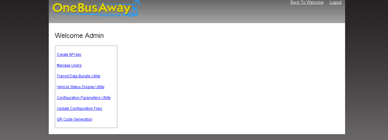
Welcome page has links to several admin utilities. Each utility is described in the following sections with the steps to use it.
User management allows an admin user to manage users in the system. An admin user can create, edit or deactivate other users in the system. This tool is available to an 'Admin' user only. Once an admin user clicks 'User Management' link on the main page, he/she is navigated to user management interface which looks like this

All the operations provided by this utility are described below
This operation creates a new user in the system. It also assigns the given credentials to this user. A user can be created by clicking on create user link. The interface for creating a user looks like this

Enter user name, password in the respective text boxes. If the user is admin check 'Is Admin' check box and click 'Submit' button. User can be created either as 'Admin' or 'Operator' but not both. If the operation succeeds, the success message appears at the bottom. Back to User Management link can be used to navigate back to user management page.
This operation edits an existing user in the system. It can change user password, user role or both. An 'Operator' can be promoted to 'Admin' role using this operation. Edit operation starts with searching an existing user on 'User Management' interface. The search control auto populates matching results when a user starts typing in the search box. User Details are displayed as soon as a user is selected from the suggestions. The user details look like this

Edit operation can be performed by clicking edit image under 'Actions' in user details table. Once edit image is clicked, the system displays edit section as follows
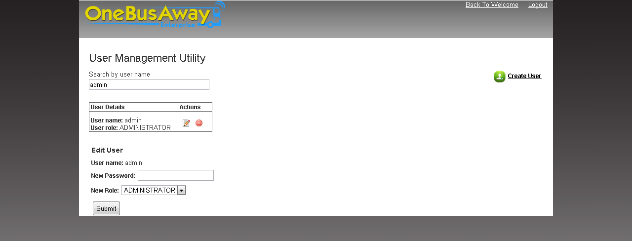
User that is being edited is displayed with user name and current role in the edit section. An admin user can now enter new password or pick a new role from the 'Roles' drop down. Once all the required changes have been made, admin user can click 'Submit' button. A success message is displayed at the bottom if edit operation succeeds.
This operation deactivates a user in the system. The deactivated user still stays in the system but his credentials are removed. The deactivated user cannot access the admin web application.
Deactivate operation follows the same process as edit operation. It begins by searching the required user and displaying his details. Once user details are displayed, an admin user can then click on 'Deactivate' image under 'Actions' in 'User Details' table. A confirmation dialog is shown once deactivate is clicked like this

A user is deactivated 'OK' button is clicked. This operation can also be cancelled by clicking 'Cancel' link in the dialog. A success message is displayed at the bottom if deactivate operation succeeds.
This tool allows an admin user to build and deploy a 'transit bundle,' or an optimized collection of route and schedule data, to the Transit Data Manager (TDM). The deployed bundle is then used by Inference Engine to provide vehicle inference data, as well as by the Front Ends for display.
This utility can be accessed by clicking Transit Data Bundle Utility link on the welcome page. Building and deploying a bundle is a five step process. These steps are shown below
This is the very first step which involves creating/selecting directory on S3. This directory acts as a source of required files in further steps of bundle building process. The user can either create or select an existing directory. The interface for creating directory looks like this
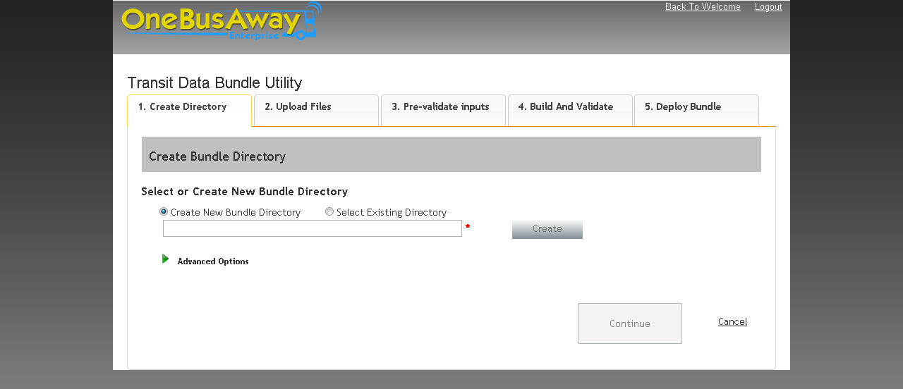
The directory name to be created can be entered in the text box. A directory is created on Amazon S3 in the configured S3 bucket after 'Create' button is clicked.
A user can select an existing directory on S3 as well. The interface for selecting an existing directory looks like this
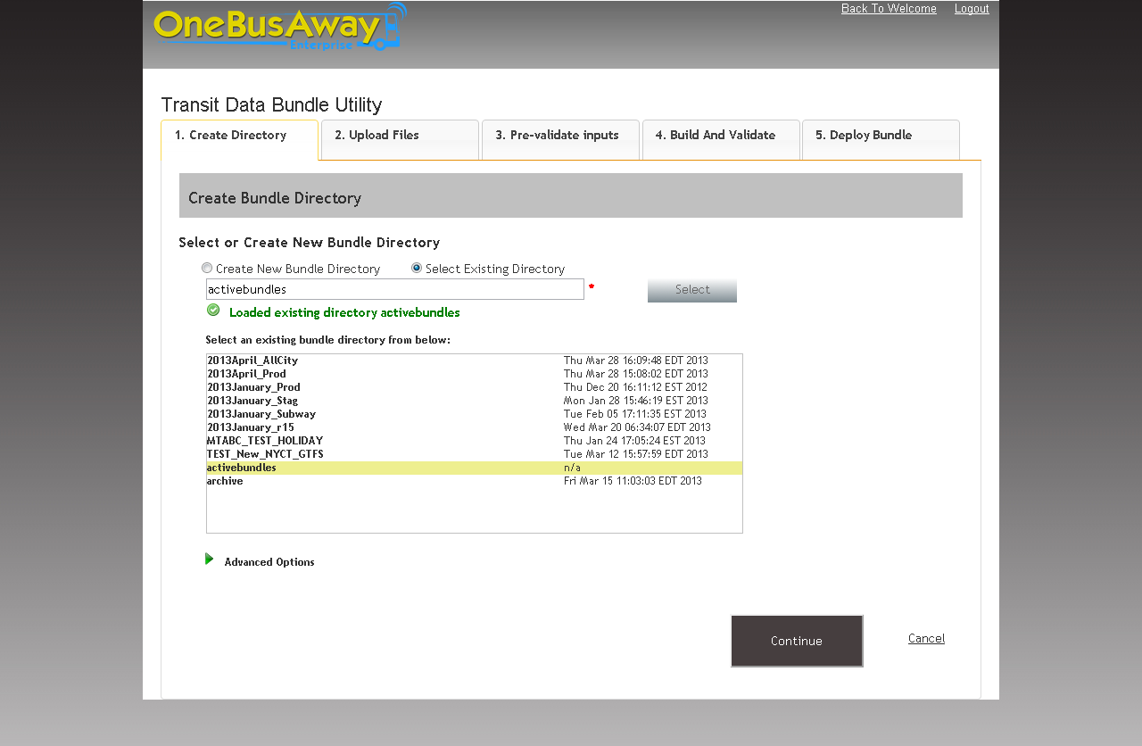
User can choose 'Select Directory' radio button to select an existing directory. Once this option is chosen, the UI displays a list of existing directories from S3 bucket. User can then choose the required directory and click 'Select' button. User can then press 'Continue' button to proceed.
This is a manual step in which a user has to upload bundle files to the created/selected directory in S3, using either the S3 console or another method. Any pre-processing that will affect the schedule data in the bundle needs to happen before uploading to the listed directories. Following image shows the UI for this
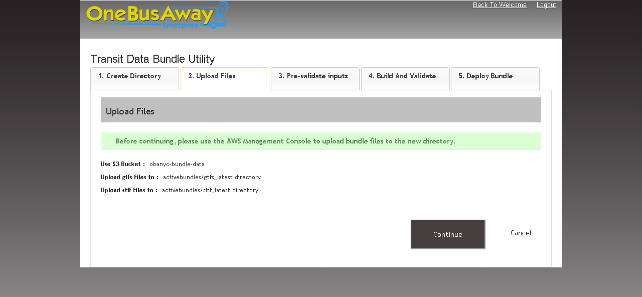
As shown in the screen shot, the tool displays exact S3 location for uploading GTFS and other schedule-related files. Once the files are uploaded on S3, user can then press 'Continue' button to proceed.
This step runs a pre-validation process on the files uploaded on S3. Currently, this step uses the GTFS Feed Validator from the Google Transit Data Feed toolset.
The user interface for validating bundle looks like this
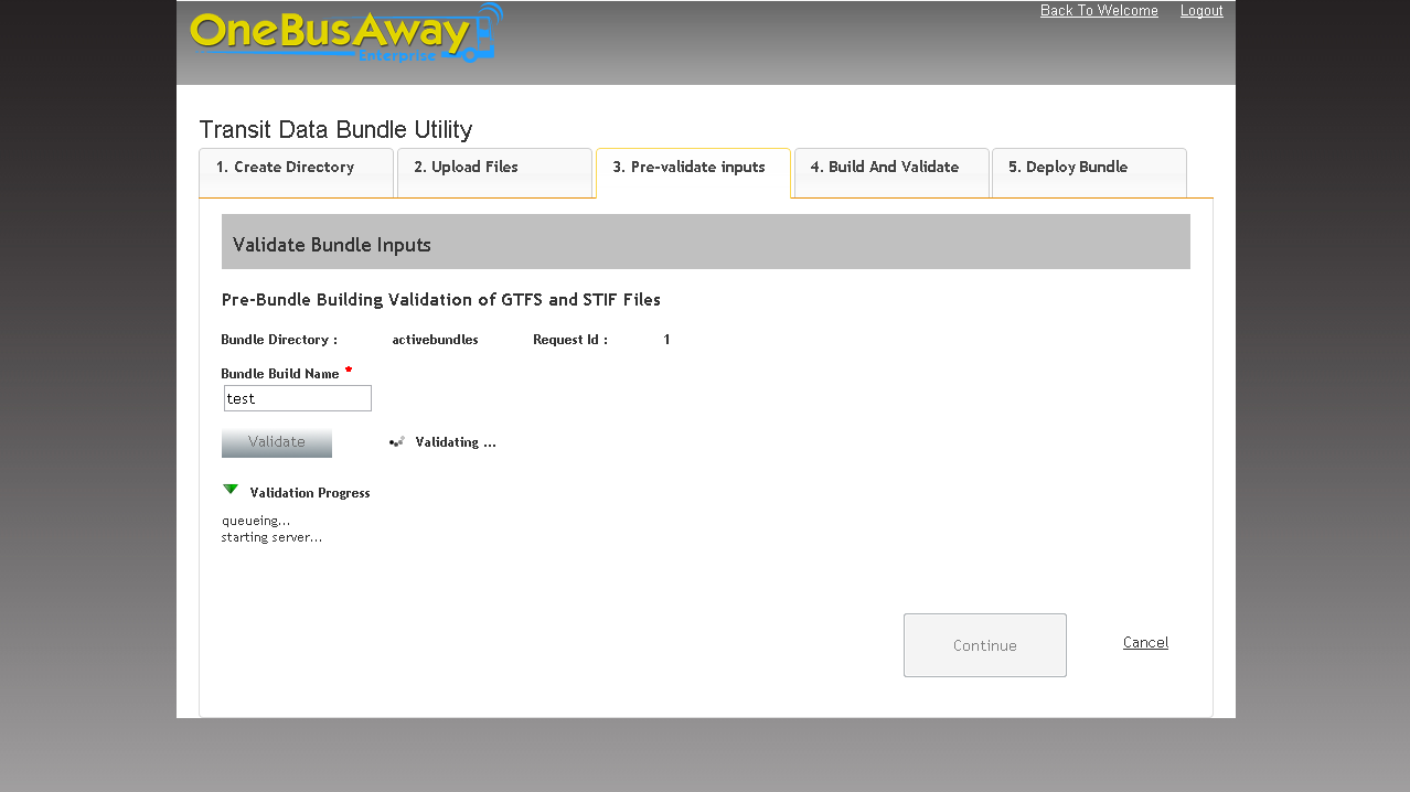
Validation process can be started by entering bundle name in the text box and then clicking 'Validate' button. A useful convention for bundle name is "General Data Set Name""Release Number""Build_Number" (e.g 2013Sept_AllCity_r01_b01).
The validation progress can be viewed by expanding 'Validation Progress' list. The process displays a list of generated .html files on the page once the validation process finishes successfully.
This step actually builds a bundle and uploads it to the required directories in S3. The user interface for building a bundle looks like this
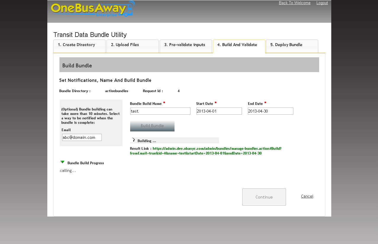
Bundle name is auto populated from the previous step. Note that the Bundle 'Start Date' and 'End Date' fields are the period of the validity of the bundle. As a bundle may be comprised of several different data sets, the start will be either the minimum of the dates in the calendar.txt of all included GTFS feeds or the current date. The end will usually be the maximum date in the calendar.txt of all included GTFS feeds.
The bundle building process begins when start and end dates are entered and 'Build Bundle' button is clicked. Optionally, user can enter an email address on the left, which will result in an email sent once the bundle is built. The UI also displays 'Result Link' which shows the location of bundle build results. A more verbose bundle build progress can be viewed by expanding the 'Bundle Build Progress' field. The output files generated can be downloaded using 'Download as Zip' button on the UI and reviewed locally.
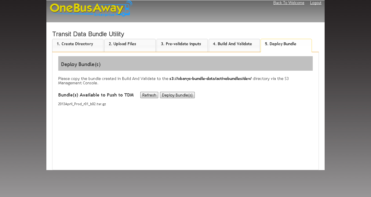
This display shows the bundles available to push to TDM. The bundle built using previous steps needs to be copied to the location specified on this page. Once the bundle is copied it can be deployed to TDM by clicking 'Deploy Bundle' button.
Note that clients of the TDM's bundle management service are configured to swap bundles on the hour to reduce synchronization issues. These clients check for bundles at 15 minutes before the hour. With that in mind, it is recommend to deploy bundles at least 20 minutes prior to the hour to allow for detection, downloading, and validation by clients.
This tool displays current status of vehicles that transmit data to the OBANYC Server. It provides an ability to monitor vehicles in service by displaying a snapshot of most recent data on the UI. This utility can be accessed by clicking on Vehicle Status Display Utility link on the welcome page. The user interface looks like this
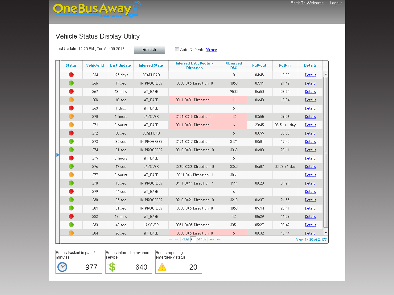
As shown in the screen shot, a grid displays vehicle data with useful information such as route, inferred DSC, pullin time, pullout time etc. It displays status of each vehicle in the first column. Status image is displayed based on vehicle's last update time and inferred state. Also inferred DSC and observed DSC columns are highlighted in red if their values differ. The grid displays 20 records at a time. Other records can be viewed by clicking page controls at bottom of the grid. The grid also displays total records at the bottom right corner.
Grid data can be auto refreshed by checking auto refresh check box. The auto refresh duration can be changed by clicking on the hyper link next to auto refresh check box. Clicking the link opens a dialog to set the refresh interval. Grid data can also be refreshed on demand by clicking 'Refresh' button. The page also displays last data update time on the left corner.
Several filters are provided on the left pane to filter grid data as required. These filters can either be used individually or with one another to filter grid data. Some notes about the filters:
- The DSC filter looks for matches starting with the input digits; the remaining filters look for exact match and do not return partially matched results.
- The Pullout Status filter defines an active pullout as a pullout record with a pullout time before the current time.
Filters can be used by entering values and clicking 'Apply' button. Clicking on 'Reset' button resets filter values only. 'Refresh' button needs to be used if it is required to reset both grid data and filters. Filters panel can be collapsed to get a better view of the results on the grid.
Summary information is displayed in boxes at bottom of the page. It provides a count of number of buses tracked in past 5 minutes, buses inferred in revenue service and buses in emergency status.
Clicking 'Details' link on any record opens a popup as shown
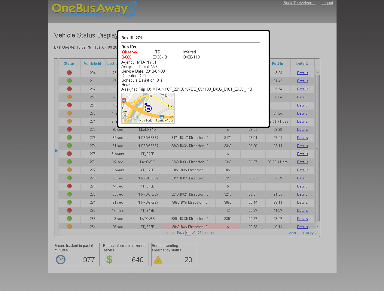
Detail popup shows even more data about a given vehicle. It shows information such as head sign, operator id, trip id etc. It also shows a map with vehicle's current location. The popup can be closed by clicking anywhere outside.
This tool allows setting up configuration parameters for the system. These configuration parameters are stored on Transit Data Manager (TDM) and are read by different components of the system. This provides flexibility to the system. This utility allows modifying configuration parameter values through a user interface. This tool can be accessed by clicking Configuration Parameters Utility from the welcome page. The interface looks like this
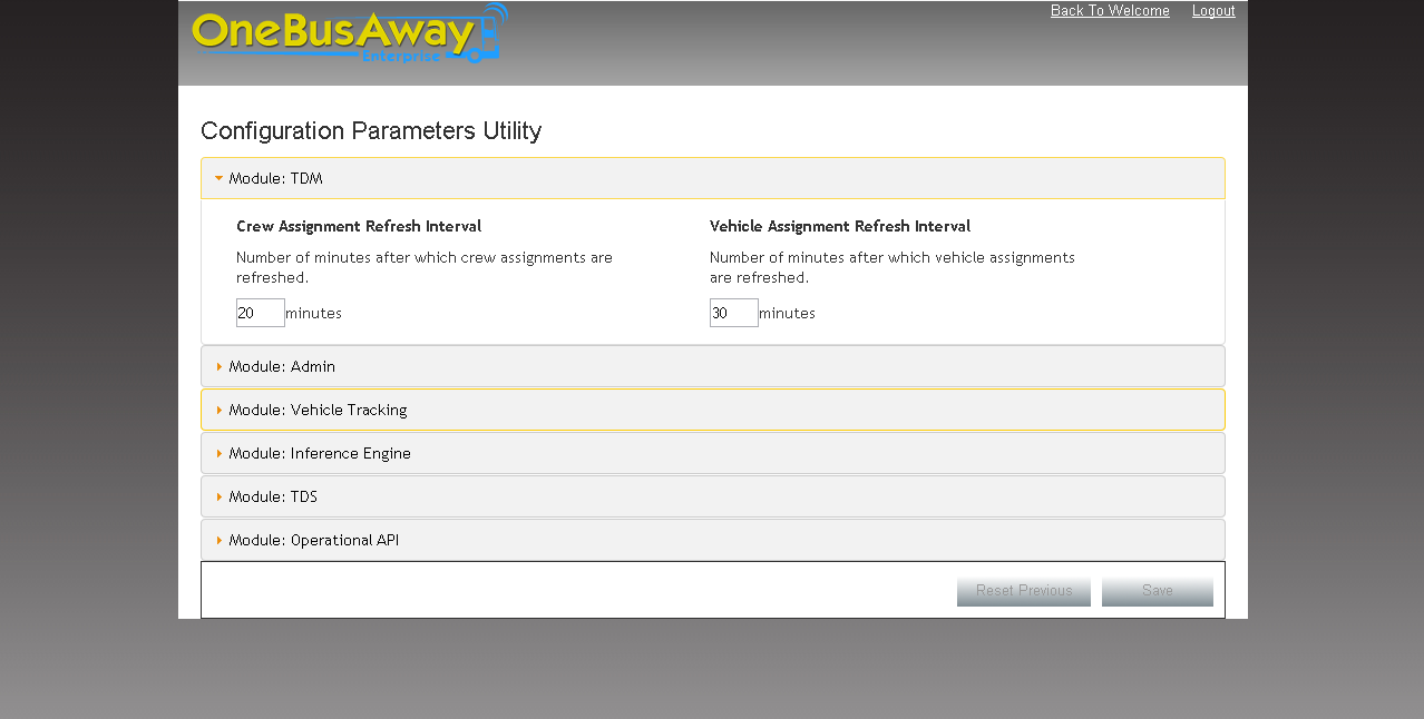
Parameters are displayed in groups according to the components they belong to. The components can be expanded/collapsed by clicking on horizontal panels on the page. A user can edit parameters and click 'Save' button. This button saves the modified values on the TDM machine. If save operation succeeds, a success message appears next to the buttons in yellow background, fading away in some time. Clicking on 'Reset to Previous' reloads the parameters in the interface. This operation wipes out any unsaved changes on the UI. It resets UI to the last saved point and is not intended to roll back any save operation.
User is presented with a confirmation box as shown below if he navigates away from the page with unsaved changes
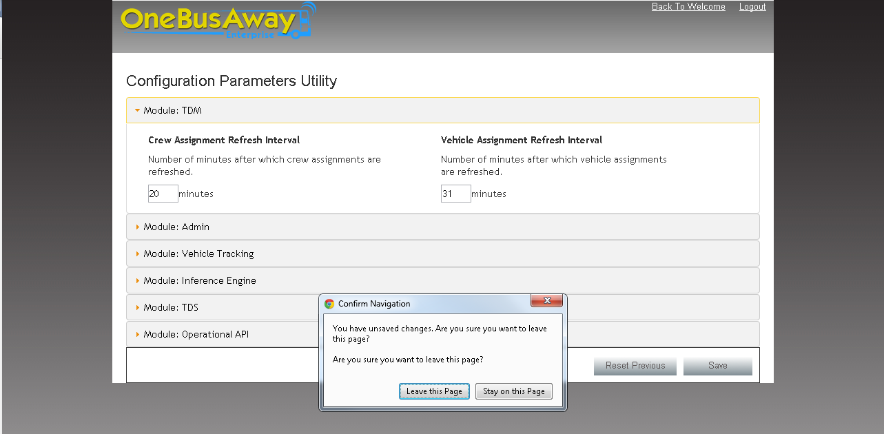
This notifies the user of some unsaved changes. User can either choose to go back to the page for saving the changes by clicking on 'Stay On Page' button or can leave the page by clicking 'Leave Page' button.
Note that clients of the TDM configuration service poll the service on 5 minute intervals; so changes may take some time to propogate throughout the system.
This tool can be used by an admin user to generate Quick Response (QR) Codes for bus stops. QR codes can either be generated individually or as a batch. This utility can be accessed by clicking QR Code Generation link on the welcome page. The interface for this tool looks like this

This screen shot shows the interface for generating individual QR codes. Admin user can enter a valid stop id and edge dimensions in the respective text boxes and click 'Generate' button. The generated QR code image is displayed at the bottom of the page if the operation succeeds.
QR codes can also be generated in batch using this tool. The generated QR codes are packaged in a zip file which can be saved in a convenient location. The interface for generating QR codes in batch looks as follows
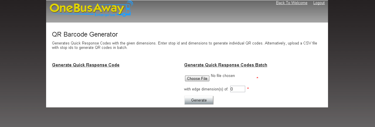
A Comma Separated (CSV) file needs to be uploaded to generate QR codes in batch. A sample file is attached. The first column is expected to be STOP_ID. A User can upload this file using 'Browse' button. This opens a file browser dialog which can be used to select the required file. Once a file is selected, user needs to enter edge dimensions for the images. Entered edge dimensions are applied to all the generated QR codes. Once user hits the 'Generate' button, the system parses the uploaded CSV file and generates a QR code image for every stop id specified in the file. User is then prompted with a dialog to save the generated zip file.
Admin user can create an API key in the system using this utility. API keys are used by several web service calls to render information on the public facing interfaces. This utility can be accessed by clicking Create API Key link on the welcome page. The interface looks like this

Admin user can enter the required API key value in the text box and click 'Create' button. Success message is displayed on the page if API key creation succeeds.
API key mangement can additionally be performed via webservices:
| URL | Operation |
|---|---|
| /api/keys/list | list all existing keys |
| /api/keys/create | creates a new, random API key |
| /api/keys/create/<keyvalue> | creates a new API key with the specified key value |
| /api/keys/delete/<keyvalue> | remotes the API key with the specified value |
The result of the above calls is JSON indicating the outcome of the operation (success/failure/error).
This tool can be used to deploy configuration files to Transit Data Manager (TDM). It currently supports deploying depot id maps and destination sign code files to TDM. This tool can be accessed by clicking Update Configuration Files link on the welcome page. The interface looks like the following image
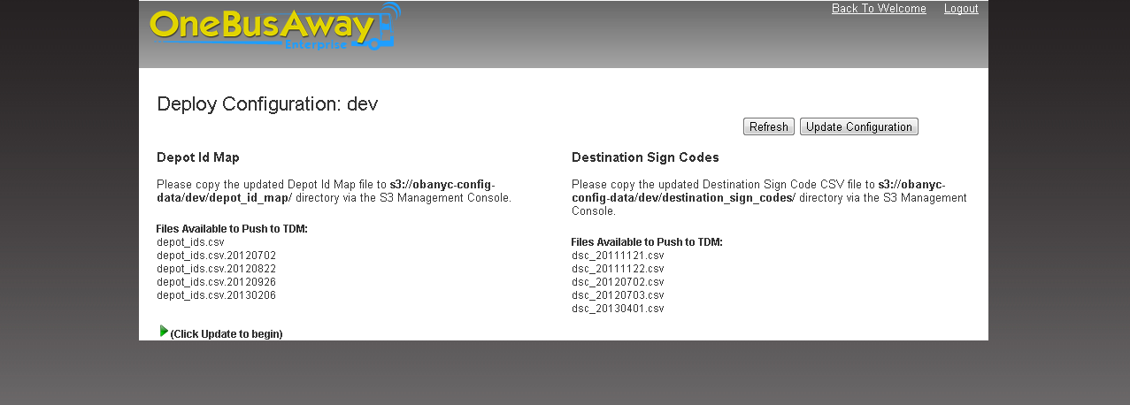
As per the instructions on screen shot, the files that need to be deployed should be manually copied to the Amazon S3 bucket listed. User can click 'Refresh' button once the files are copied to S3. This queries S3 to check if it has been updated and displays the results under Files Available to Push to TDM list on the page. User can then click 'Update Configuration' button for deployment process to begin. Success message is displayed if the deployment succeeds, error message is displayed otherwise.
The Depot Id Map file is specified in configuration to be depot_ids.csv and used by the DepotIdTranslator as such. By convention, older files are timestamped with a suffix of the date they were created or moved aside on, but this is for storage purposes only; it is not used by the system.
Relevant DSC files are determined by the DscManualUploadDateTimestampFilePicker. It looks for most recent file based on the timestamp file name inclusion. Only files of the format dsc_YYYYMMDD.csv are considered; any other file will be ignored.