Analyzing DCC with an Oscilloscope
For this, I obtained a SainSmart DSO Note II DS202 Oscilloscope; a pretty basic, but also pretty cheap, pocket sized oscilloscope. The probe it came with needed assembling, and then was simple enough to attach to the track with the probe on one rail, and the ground clip attached to the other.
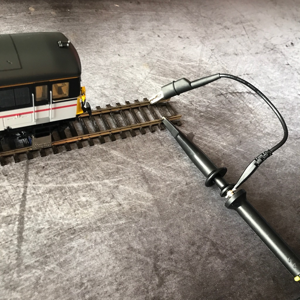
The other end goes into the Ch-A port of the oscilloscope, and with a DCC signal on the track, something should be visible on the screen. At least after a few different settings are adjusted.
Voltage: set for the Channel, and is the voltage step for each individual line on the display. For OO gauge 15V is pretty typical on the track, so setting this to 5V would make the DCC signal pretty visible.
AC/DC: set for the Channel. Since DCC is a DC signal, set this to DC.
TimeBase: set globally, and is the time step for each individual line on the display. More on this later when we get to recording, but since the period of DCC is 112µs for a 1, and 200µs for a 0, 0.1ms seemed like a reasonable starting point.
Trigger: set globally. This allows some degree of synchronisation on the display, I set it to a falling voltage on Channel A.
Unfortunately even with all this set up right, the signal didn't look right on the display:
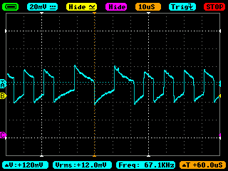
Not only is the the signal malformed, but the Vrms reading is 12mV rather than the expected 15V. The probe that comes with the oscilloscope claims to be 1X attentuation, and that's what the oscilloscope is set to.
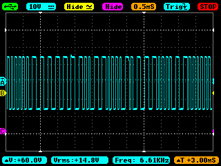
Fortunately I had also ordered a couple of spare set of RioRand Probes, so I tried these instead, and immediately fixed the problem:
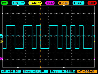
Now everything is at it should be! We can clearly see the short 1s and the longer 0s in the signal.
The oscilloscope has an adjustable buffer in the X-Window menu; weirdly from what I can tell, the buffer is actually data that has yet to be displayed rather than a history of what was previously displayed. It still serves our purposes though.
The time between samples stored in the buffer is related to the TimeBase that you set, a little experimentation suggests that 25 samples are stored in the buffer per TimeBase. Thus setting the TimeBase to 0.1mS means that there will be one sample every 4µs; and with the buffer size to 8K, that means a total recording duration of only 32mS.
To analyze the DCC signal, we don't need anywhere near that level of detail, but we would prefer to have a longer recording. Upping the TimeBase a couple of steps to 0.5mS decreases the sample rate to just one every 20µs, but that still provides 5–6 samples for a DCC 1 bit and 10+ for a 0 bit, which is plenty to decode it. And it has a huge advantage in that it increases our recording time to 163mS.
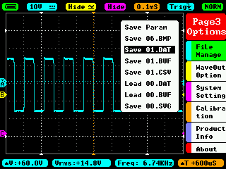
Getting the buffer onto a computer is relatively easy, it can be saved to internal storage from the third menu page in a few different formats.
CSV outputs a comma separated file with a sample value for each channel on each line. The values seem to be related to the Post and Voltage values, with the number incremented by 25 for each Voltage step, and the 0V value being equal to the Post value for that channel.
BUF outputs a raw binary file with one byte per channel. Each byte is in the range 0–255, and again seem related to the Post and Voltage values of the channel in question.
SVG outputs a vector graphics image file that renders the entire buffer.
Reading the files is as simple as plugging the USB cable into a computer, though I found I had to disconnect and reconnect the cable after each save otherwise the file wouldn't necessarily be visible.
Sometimes we just want to look at the packet without analyzing in depth. Pressing the ⏯ button on top of the oscilloscope pauses the display and allows us to pan the buffer on screen using the X_Window menu. Holding down the ⏯ button takes a screenshot and saves it out as a BMP file.
This can often be enough to see a single DCC packet and read it.