Using PWM to generate DCC signal
Using the GPIO directly to generate the DCC signal works at a basic level, but doesn't provide us the accurate timing that we need to meet the requirements of the specification.
Fortunately the Raspberry Pi includes additional hardware that can control the GPIO pins for us in the form of the Pulse Width Modulator (PWM).
The PWM is used by combining three different peripherals in the Raspberry Pi together; the GPIO controller that we've already used, in order to provide an output for the PWM; the PWM itself; and a clock that sets the rate at which the PWM operates.
What the PWM itself does is set the amount of time that the GPIO is high vs low, with a number of different programming modes to achieve different methods of doing so.
We'll look at each of these moments in turn, after examining basic setup. As with the GPIO code, we'll access the registers through /dev/mem:
let peripheralAddressBase = 0x3f000000
let peripheralBlockSize = 0x1000

let memFd = open("/dev/mem", O_RDWR | O_SYNC)
guard memFd > 0 else { fatalError("Couldn't open /dev/mem") }
defer { close(memFd) }The speed at which the PWM runs at is set by the PWM Clock, unfortunately the datasheet is missing the documentation on this, but there is a separate datasheet available that does, specifying the offsets within the larger clock registers for programming them.
let clockRegistersAddress = peripheralAddressBase + 0x101000

let pwmClockControlOffset = 0xa0
let pwmClockDivOffset = 0xa4

guard let clockRegisters = mmap(nil, peripheralBlockSize, PROT_READ | PROT_WRITE, MAP_SHARED, memFd, off_t(clockRegistersAddress)) else { fatalError("Couldn't mmap clock registers") }

let pwmClockControl = clockRegisters.advanced(by: pwmClockControlOffset).assumingMemoryBound(to: UInt32.self)
let pwmClockDiv = clockRegisters.advanced(by: pwmClockDivOffset).assumingMemoryBound(to: UInt32.self)
First we have to stop the clock from running, and wait for the BUSY flag to go away. Every write needs the initial 0x5a as the "password" for the clock manager, so just writing 0s for everything else should disable it.
pwmClockControl.pointee = 0x5a000000

// Docs say this is debug only, but the above didn't work out for me.
usleep(10)
pwmClockControl.pointee = 0x5a000000 | 0b100000

while pwmClockControl.pointee & 0b10000000 != 0 { }
With the clock disabled, we can adjust the rate at which it ticks. This is controlled by four things: the source, the MASH control, the integer part of the divisor, and the fractional part of the divisor. There's a useful online calculator to figuring out the exact values.
The two most interesting clock sources are the Oscillator (OSC) which runs at 19.2 Mhz, and the Phase Locked Loop (PLL)'s fourth source (PLLD) which runs at 500 MHz.
With the MASH control set to MASH-0, only the integer part of the divisor is used, and is a value from 2 to 4,096 that divides the clock source's basic rate down to a lower rate. For example if we want a 1 MHz clock, with the 500 MHz PLLD source, we can set the integer divisor to 500 to achieve it (500 Mhz ÷ 500 = 1 Mhz).
To do the same using the slower oscillator clock source we could only divide by 19, so would end up with a resulting clock rate of 1.01 Mhz—slightly faster than we intended.
Since the highest possible value for the divisor is 4095, which means that the slowest possible clock rate for the PLLD source is 122 KHz, while for the OSC it's around 4.7 KHz.
We'll come back to this later, for now, let's just set 1 MHz the easy way and use that as a test signal. We introduce a slight delay afterwards to ensure the clock hardware has been programmed before enabling it again.
pwmClockDiv.pointee = 0x5a000000 | UInt32(500 << 12)

pwmClockControl.pointee = 0x5a000000 | 0b10000
usleep(10)
pwmClockControl.pointee = 0x5a000000 | 0b10000 | 0b0001
while pwmClockControl.pointee & 0b10000000 == 0 { }
Note the double-set of the control value, since we cannot "change" the source while enabling.
We need an output for our PWM pulses; reading through the datasheet we can see that there are a number of different pins that have can receive the output of either PWM0 or PWM1 by changing their function to one of the alternates.
let gpioRegistersAddress = peripheralAddressBase + 0x200000

let gpioPin = 18

guard let gpioRegisters = mmap(nil, peripheralBlockSize, PROT_READ | PROT_WRITE, MAP_SHARED, memFd, off_t(gpioRegistersAddress)) else { fatalError("Couldn't mmap GPIO registers") }

let gpioFunctionSelect = gpioRegisters.assumingMemoryBound(to: UInt32.self).advanced(by: gpioPin / 10)

gpioFunctionSelect.pointee &= ~(0b111 << UInt32((gpioPin % 10) * 3))
gpioFunctionSelect.pointee |= 0b010 << UInt32((gpioPin % 10) * 3)
This code is explained more thoroughly in the GPIO example, the difference is in the value stored in Function Select to set the pin to the alternate function that matches PWM0 for this pin.
I've picked GPIO18 simply because it's in a convenient place on the header, for this we set to alternate function 5.
As mentioned above, the PWM has a few different modes that it can run in. Setting the mode is handled through the PWM Control register, while the details are handled through the PWM Channel 1 Range and PWM Channel 1 Data registers.
let pwmRegistersAddress = peripheralAddressBase + 0x20c000

let pwmControlOffset = 0x00
let pwmRange1Offset = 0x010
let pwmData1Offset = 0x14

guard let pwmRegisters = mmap(nil, peripheralBlockSize, PROT_READ | PROT_WRITE, MAP_SHARED, memFd, off_t(pwmRegistersAddress)) else { fatalError("Couldn't mmap PWM registers") }

let pwmControl = pwmRegisters.advanced(by: pwmControlOffset).assumingMemoryBound(to: UInt32.self)
let pwmRange1 = pwmRegisters.advanced(by: pwmRange1Offset).assumingMemoryBound(to: UInt32.self)
let pwmData1 = pwmRegisters.advanced(by: pwmData1Offset).assumingMemoryBound(to: UInt32.self)The "default" mode of the PWM is the one we get by enabling the PWM with all other option bits set to zero.
It's controlled by the PWM Channel Range and Data registers, where by the ratio of outputs that are high vs. low is set to the ratio of the Data register vs the Range register.
For example, we can set the Range to 1,000, and the Data to 250, and then enable the PWM:
pwmRange1.pointee = 1000
pwmData1.pointee = 250
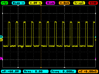
pwmControl.pointee = 0b00000001In this mode 25% of the individual bits will be high, with the length of the bit and bit rate determined by the PWM clock. Thus we expect to see a 3V high for 1µs, followed by a low for 3µs, repeatedly. Connecting up an oscilloscope, this is exactly what we see:

I'm not sure whether the unclean shape of this is an artifact of the oscilloscope's sampling speed, or simply of the high switching range of the PWM and high resolution that we're looking at it.
It's important at this rate of switching to have the oscilloscope's TimeBase set correctly; in the above it's set to 1.0µs, accidentially setting it to lower resolutions can produce very strange views as the oscilloscope samples less frequently and tries to intepret what it's recording.
While useful for creating a high frequency pulse to "dim" an LED, this isn't the kind of pulse we want for the DCC signal, so onto the next mode.
An alternate mode for the PWM is the mark-space (M/S) mode. The mode is still controlled by the Range and Data registers, with them interpreted as a ratio, except that instead of distributing the highs across the entire range, the output is high for the number of bits specified in Data, and then low for the remaining number of bits specified in Range.
Using the same sample Range and Data values, but adjusting the mode for the PWM:
pwmRange1.pointee = 1000
pwmData1.pointee = 250

pwmControl.pointee = 0b10000001
We would expect to see the output high for 250 bits, and then low for 750 bits (1000 - 250 = 750):
Note that the oscilloscope TimeBase is a lot higher in the above image, with each pulse occuring every microsecond, and lasting one quarter of one. It looks a lot cleaner too.
By adjusting the clock, range, and data, we can achieve the clean on/off we need for DCC; but we would have to continually adjust the range and data values to handle the different lengths of 1s and 0s. This mode seems ideal for servo motors, but still isn't quite what we need for DCC.
The third alternative mode for the PWM is the serializer mode. In this mode, the Range and Data registers are interpreted quite differently.
The Data register specifies a bit pattern which the PWM will output, the length of each bit is, as in all cases above, set by the PWM clock. When a bit is 1, the PWM will output high (3V), and when a bit is 0, the PWM will output low (0V).
The Range register specifies the number of bits in Data that will be used. When this is less than 32, the register is truncated with only the number of specified bits, starting from the most significant, used and repeated. When the number is greater than 32, the full Data register will be transmitted, followed by the pin remaining low for the remainder of the time in Range.
Thus we can produce entirely custom bit patterns:
pwmRange1.pointee = 32
pwmData1.pointee = 0b11110000111100001111111100000000

pwmControl.pointee = 0b00000011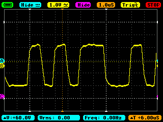
Now we have something that looks like a DCC signal! The clock timings and bit lengths are wrong for DCC, but as we see above, those can be flexibly customized. I've documented my thoughts on the correct values for the clock elsewhere.
The downside to this mode though is that we only have 32-bits of data available to transmit, that are repeated. We're not quite there yet.
There is fortunately a way to increase the amount of data for the serializer mode, which is to use the PWM FIFO instead of the Data register. This is a separate register to which we can write up to eight separate data elements, in the same format we would otherwise have written to the Data register. The PWM processes them in first-in-first-out order.
Before we begin, we clear the FIFO of existing data:
pwmControl.pointee = 0b1000000Then we write to it by repeatedly writing to the PWM FIFO Register:
let pwmFifoOffset = 0x18

let pwmFifo = pwmRegisters.advanced(by: pwmFifoOffset).assumingMemoryBound(to: UInt32.self)

pwmFifo.pointee = 0b11110000111100001111111100000000
pwmFifo.pointee = 0b11111111000000001111111100000000
pwmFifo.pointee = 0b11110000111100001100110011001100
pwmFifo.pointee = 0b11111100000010101111000011110000
The Range register still applies, specifying the width of the 32-bit FIFO entry to use, so we set that as before, before enabling the PWM and instructing it to use the FIFO for the serializer mode:
pwmRange1.pointee = 32

pwmControl.pointee = 0b00100011
Eight 32-bit entries gives us a total of 256 bits of information, this seems like a lot, but once we start encoding the DCC signal it soon gets reduced. Even with the most frugal approach, that is only room for 110 "1 bits" or 55 "0 bits" after the preamble. Enough for one command, fortunately.
However the best part about the FIFO is that it can be written to as it drains, with each new write appending to the set to be sent. This can be done at a lot slower rate than the clock, for example if we use the compromise 14.5µs per bit rate, the FIFO will still take 3.7ms to drain and need refreshing 269 times a second.
Meeting these is much more realistic, and there's still further hardware assistance we can use.