HW_ILoop
The Telex adapter hardware must source a constant (regulated) current of 40mA, switch the current for transmitting data and observe the current for receiving data from the Telex.
The current loop is specified in "TW39".

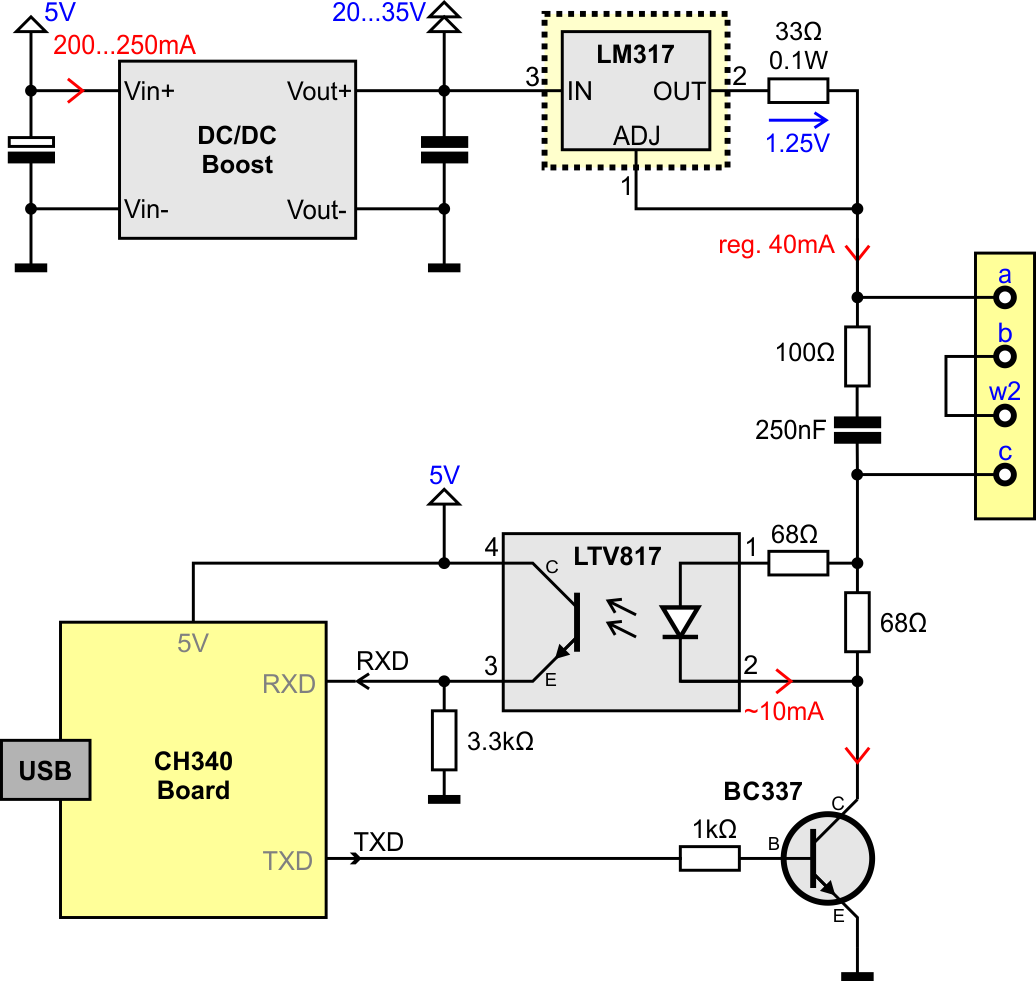
To use a Telex as an USB-device you can use an USB-to-serial-TTL converter based on a CH340 chip (other chips from FTDI and Prolofic don't work at 50 baud, 5 data-bits, 1.5 stop-bits).
The commutate circuit (drawn in cyan) is optional and only needed when the telex is using a FSG. Without a FSG the cyan area can be removed.

To use router and FSG functionality the adapter hardware can be connected directly to a Raspberry Pi.

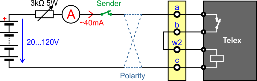
Simplified example of a connection between a teletype and the VST (central office).
In old days the VST has a fixed power supply with 120 volt and a potentiometer for each line (end user) which was adjusted to 40 mA by a VST technician.

The easiest way to supply the 40 mA is a potentiometer and an ampere meter as in the old days.
The given voltage depends on your teletype hardware and can vary between 20 and 120 volt. For more infos on power supply see page Power for Current-Loop.
Note: On voltages below 60 volt the 1 kOhm resistor should be removed
If anything is changed (teletype, FSG, voltage, ...) the potentiometer has to be adjusted. To avoid permanent adjusting (and other problems) the following schematics use a current regulator.
To simplify the device an adjustable DC/DC boost converter board (from China) is used to get a voltage of 20...35V. The voltage regulator LM317 is used as a fixed current source to get the 40mA. The LM317 works as a linear regulator and must be mounted on a heat sink.

Note: The LM317 is designed for a maximal voltage of 35V. A higher voltage can damage the chip
Hack: Use 2 or 3 LM317 (with 33 Ohm resistor) in series to split the voltage. Don't forget to isolate the sink areas
With 2 Transistors a current regulator is implemented with a voltage tolerance of 120 volt. The TIP47 works as a linear regulator and must be mounted on a heat sink.

Note: At a supply voltage of 60V a continuous power of about 2W have to be handled by the TIP47 and its heat sink
Note: The regulator can be combined with the transmitter. See examples below
To send data to the Telex the current loop must be switched. A current of 40mA means High, an open loop (no current) means Low. The simplest way is to use a transistor switching to GND.
The following schematics switches to GND. This simplifies the circuit and reduce the voltage drop on the transistor to less than 1V. Other solutions with the switching transistor in the middle of the loop have a voltage drop of 5V to 10V.
The simplest way is to use a small NPN transistor.

The transmitter has effectively no voltage drop on the current loop (< 0.2V). No heat sink or big transistor is needed.
Alternatively, to a bipolar transistor a logic level FET can be used.

To get data from the Telex the current must be observed. A current of 40mA means High, an open loop (no current) means Low.
For galvanic decoupling an opto-coupler is used.
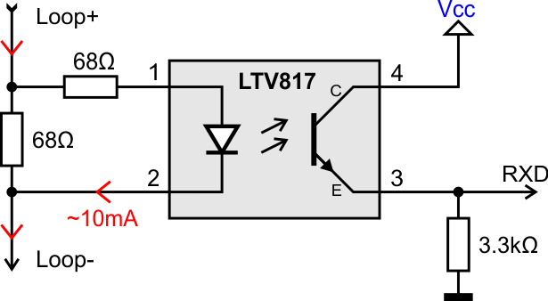
As opto-coupler a LTV817 or PC817 is recommended. All other coupler with coupling factor > 50% should also work.
The receiver has a voltage drop on the current loop of about 2V.
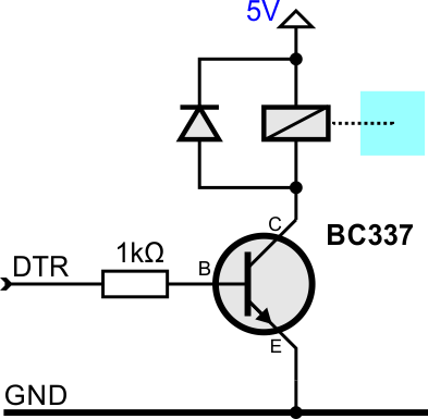
To signal the FSG (dialing and switching device) an established connection, the polarity of the current loop is reversed with a relay.
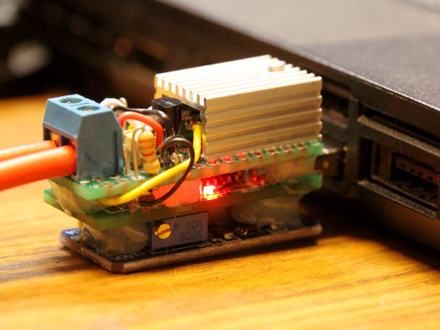
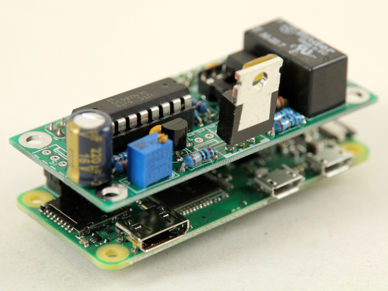
This is the first approach with a USB to TTL adapter (middle), a DC/DC converter (bottom) and a self-made-board (top) for current regulator, reading and controlling the loop.
This can be used with a Windows-PC, Linux-PC, Mac (not tested) and Raspberry Pi.
Details at Example_USB
For a stand-alone-version a Raspberry Pi Zero W is used with a DIY adapter board.
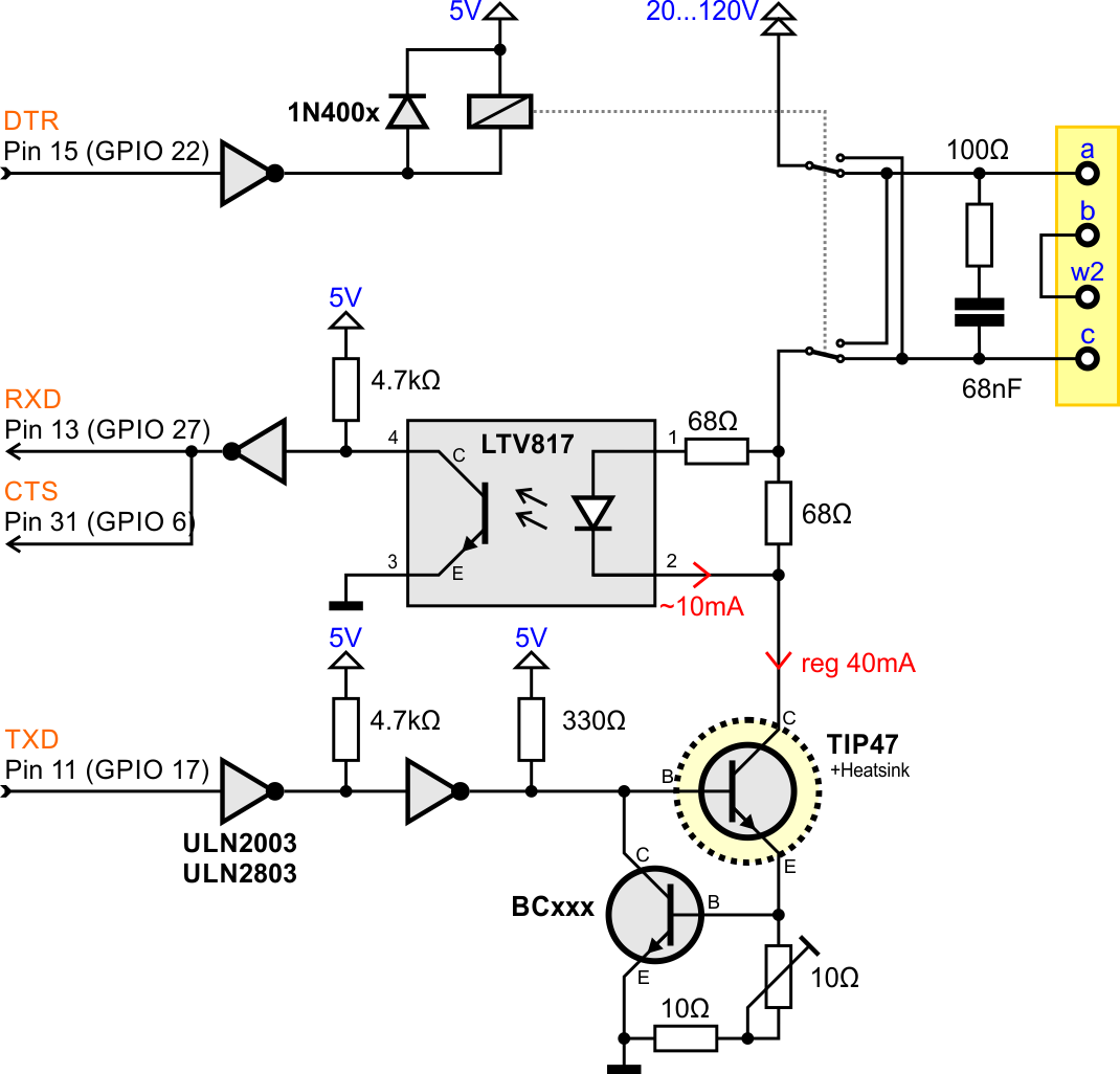
This is designed for Raspberry Pi but with a CH340-serial-adapter this can be also used with a Windows-PC, Linux-PC, and Mac (not tested).
Details at Example_RPi

-
Local use
-
i-Telex
-
Advanced Topics
-
Tools & Gadgets
-
TW39 (current loop)
-
ED1000 (FSK modulation)
-
V.10 (TeKaDe FS200, FS220)
-
SEU-M-board based
- with Austrian AGT (Ö-AGT, current loop)
- as replacement for SEU-B card inside LO2000, LO2001, LO3000