CAD and CAM workflow notes
Quick links
DISCLAIMER! This section is not intended to be complete guide to 2D/3D design or CAM, but rather a compilation of quality resources and knowledge specific to the CNC machine itself. The world of CAD/CAM can be a nightmarish rabbit-hole, but if you stay focused on your project(s) and buddy up with an experienced, friendly TC Maker member you can get stuff done easier than you'd think!
 Computer-aided design (CAD) is a piece of software that allows you to create 2D designs or 3D models that accurately represent the thing you want to create. Different programs are appropriate for different types of objects, so don't be afraid to try out more than one and see what works for you!
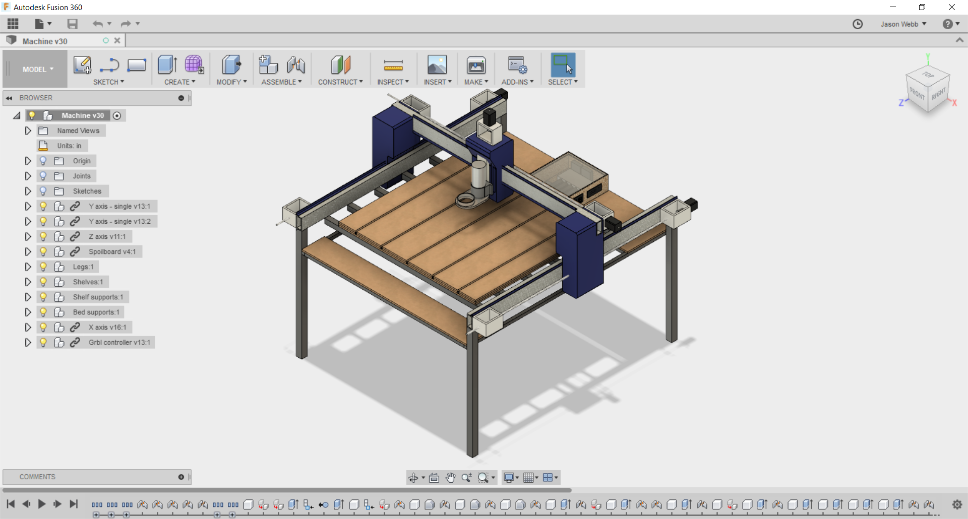
Fusion 360 is recommended for new users due to its integrated CAM capabilities, which allow you to move seamlessly between design and toolpath generation without having to learn multiple programs or fuss with file format compatibility issues.
- Make sure your design is no larger than the X/Y/Z size of the machine.
- Think ahead to how you plan to secure your workpiece to the spoilboard, and make sure you have enough extra room in your design for clamps, plastic nails, or whatever fixturing method you want to use.
- Be aware of the constraints of the machine, and avoid using features that are impossible to reach or would require risky tool changes. For example, overhangs cannot be easily achieved because the spindle is rigidly mounted perpendicularly to the spoilboard.
- Always consider the size of the end mill(s) / router bit(s) you plan to use to fabricate your part while you are designing. Is there enough space for it to get in there and move around?
- Be aware of the inside corner problem, and be sure to add dogbone or T-bone fillets to your design as needed.
- If you want to use a piece of CAD software that you haven't seen many people use for CNC work, test it out with your CAM program before you invest too much effort in it.
 Just about any vector art program that can output in the vanilla SVG or DXF format can work for CNC. However, some low-end design software (like Inkscape) can sometimes do a bad job of exporting with the right flavor of SVG/DXF that is expected by your CAM software, so be sure to try a test design before doing too much real work.
- Fusion 360
- Illustrator ($$$)
- Vectric Cut2D or VCarve ($$$)
- Inkscape
- Easel (web-based)
- MakerCAM (web-based)
 Whichever program you choose to use for 3D modeling should be capable outputting manifold (watertight), well-formed STL or OBJ models.
- Fusion 360 (recommended)
- Tinkercad (web-based)
- Onshape (web-based)
- OpenSCAD
- Blender - tricky to get units and file format correct, but very powerful for organic modelling!
- Rhinoceros ($$$) - add Grasshopper for extra awesomeness!
- Meshmixer
- Sketchup is NOT recommended, as it does not do a good job of exporting 3D models for use elsewhere.
Industry-level 3D modeling and animation packages like Maya, 3DSMax, and Cinema4D might also be used, but tend to do a bad job of exporting well-formed manifold meshes necessary for fabrication.
| Program | Tutorial |
|---|---|
| Fusion 360 | Learn Fusion 360 in 60 Minutes |
 Computer-aided manufacturing (CAM) is a piece of software that takes as input either a 2D or 3D design file (made in a CAD program) and generates toolpaths (G-code) for the machine to follow in order to carve that design into or out of a piece of material (called "stock").
In production environments CAM is taken extremely seriously and can cost many thousands of dollars and take a very long time to learn how to do well. The more efficient the toolpaths, the more parts you can produce per hour, which means more profit.
However TC Maker is not a production environment, so we don't need to as obsessed with efficiency. This means that we have a lot more (and cheaper) software options available. Though this is a bit of a double-edged sword - for every free, easy-to-use CAM package there are likely dozens that are pretty unpleasant to use and require a huge amount of overly-specific knowledge.
- Tabs are your friend! Use them whenever you can to prevent loose parts from flying across the room or worse, damaging the machine.
- Don't get too ambitious with speeds, feeds and cut depths. This is not a production-quality machine, so don't push it like one!
- Use a conservative feedrate to start with, because you can actually increase or decrease it on the fly when running the machine (up to 200%).
- Keep the step down, or depth of each pass, no larger than 1/2 the diameter of the end mill. For example, when using a 1/4" diameter end mill, make each pass 1/8" deep or less. Smaller step down means less material to cut per pass, so you can push the feedrate up, possibly reducing overall cutting time.
- Ramping into cuts can significantly reduce stress on the tool and prolong it's life.
- Take note of where the origin is being placed. This is where you will move the spindle to when its time to run your job.
- Accurately measure the real thickness of your workpiece (stock) using calipers at multiple places. Help preserve our spoilboard!
 The topic of speeds and feeds is one that makes CNC work more difficult to jump into than other digital fabrication technologies like 3D printing or laser cutting. Nonetheless, understanding the fundamental principles at work is essential to your success in using the machine with a minimal amount of frustration. Firstly, some definitions:
- Feedrate is the linear movement speed of the machine, measured in inches per minute (IPM)
- Speed is the rotational speed of the spindle, measured in rotations per minute (RPM)
When the feedrate and speed aren't balanced correctly, all sorts of unpleasant (and costly) things can happen, including:
- End mills breaking (too much feedrate, too little speed).
- End mills softening due to excess heat, causing dulling and breaking (too much speed, too slow feedrate).
- Materials burning, melting, or even catching fire due to friction (too much speed, and/or too slow feedrate).
What makes this topic so hard to teach is that every machine is different, with it's own combination of end mills, spindle, linear motion system and more. The best we can do is mindfully experiment with scrap material, then record and share what works for us on this particular machine.
If you'd like to learn more about this topic it is recommended that you become familiar with the concept of the sweet spot.
When you have some success with a material please contact me (Jason Webb) and let me know what feedrate and speed you used so I can share it here!
| Category | Parameters | Notes | |||||||||||||||
|---|---|---|---|---|---|---|---|---|---|---|---|---|---|---|---|---|---|
| Wood |
|
▪ Heat from friction can weaken, even burn up tool. ▪ Heat can also burn the wood - be very careful! ▪ Plywood and MDF can be hard on tools, so do you research. ▪ Good surface finish can be tricky due to fiber structures of wood. Look into down-cut and compression cut end mills. |
|||||||||||||||
| Plastic |
|
▪ Too much heat can melt plastics. ▪ Too much force can crack, splinter, or shatter plastics. |
|||||||||||||||
| Foams |
|
||||||||||||||||
| Other |
|
- gcodetools for Inkscape
- Easel (web-based)
- MakerCAM (web-based)
- Fusion 360 (recommended)
- MeshCAM ($$$)
- Vectric Cut2D or VCarve ($$$)
- CamBam ($$$)
A post processor is a piece of software that alters the initial raw G-code created by the CAM software by adding any proprietary codes or formatting that your particular CNC machine expects. Most of the time this functionality is built into whatever CAM program you are using, but its good to be aware of this step.
Regardless of the CAM package you choose, try to make sure that the G-code you end up with is in the LinuxCNC or EMC2 format. If you don't know, that's OK - you can simulate the G-code on the CNC machine's computer before trying to run it!
| Program | Tutorial |
|---|---|
| Fusion 360 | ▪ Overview of Fusion 360 for CNC Routers (Chair Design) ▪ CNC Router with Fusion 360, Bookshelf Tutorial |