Mechanical
Quick links
X axis - Y axis - Z axis - Spoilboard
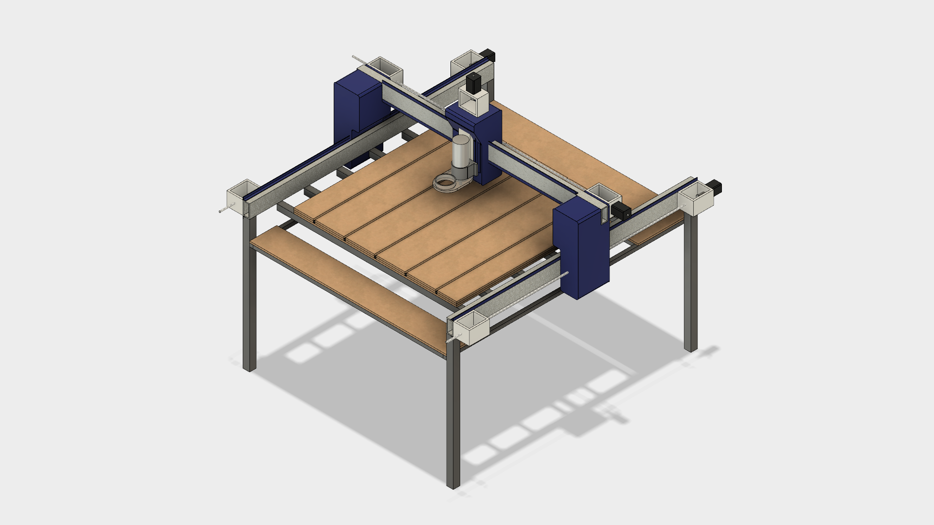
Explore the complete CAD model at http://a360.co/2tk27D5
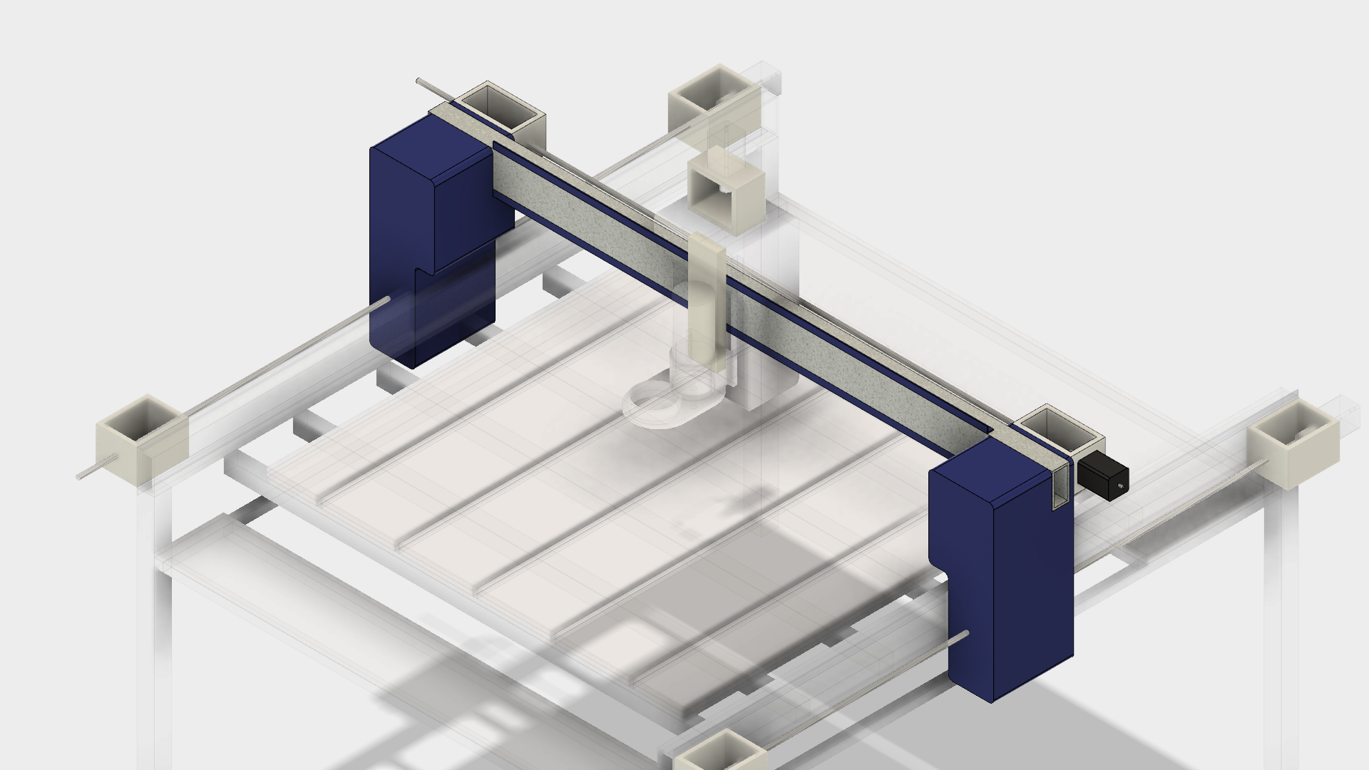 [TODO: add isolated CAD image of X axis assembly]
- Max travel = ???
- Endstops = min and max
- Leadscrew = 1/2" x 8 TPI ACME, 8 starts
- Gantry end assemblies (painted blue) are made of MDF and show significant signs of wear.
- Holes used for v-wheels mounting bolts have become worn down over time and irregularly elongated, leading to occasional jamming.
- Threaded rods being used for rigidity on gantry ends have noticeably bent some parts of the assemblies inwards.
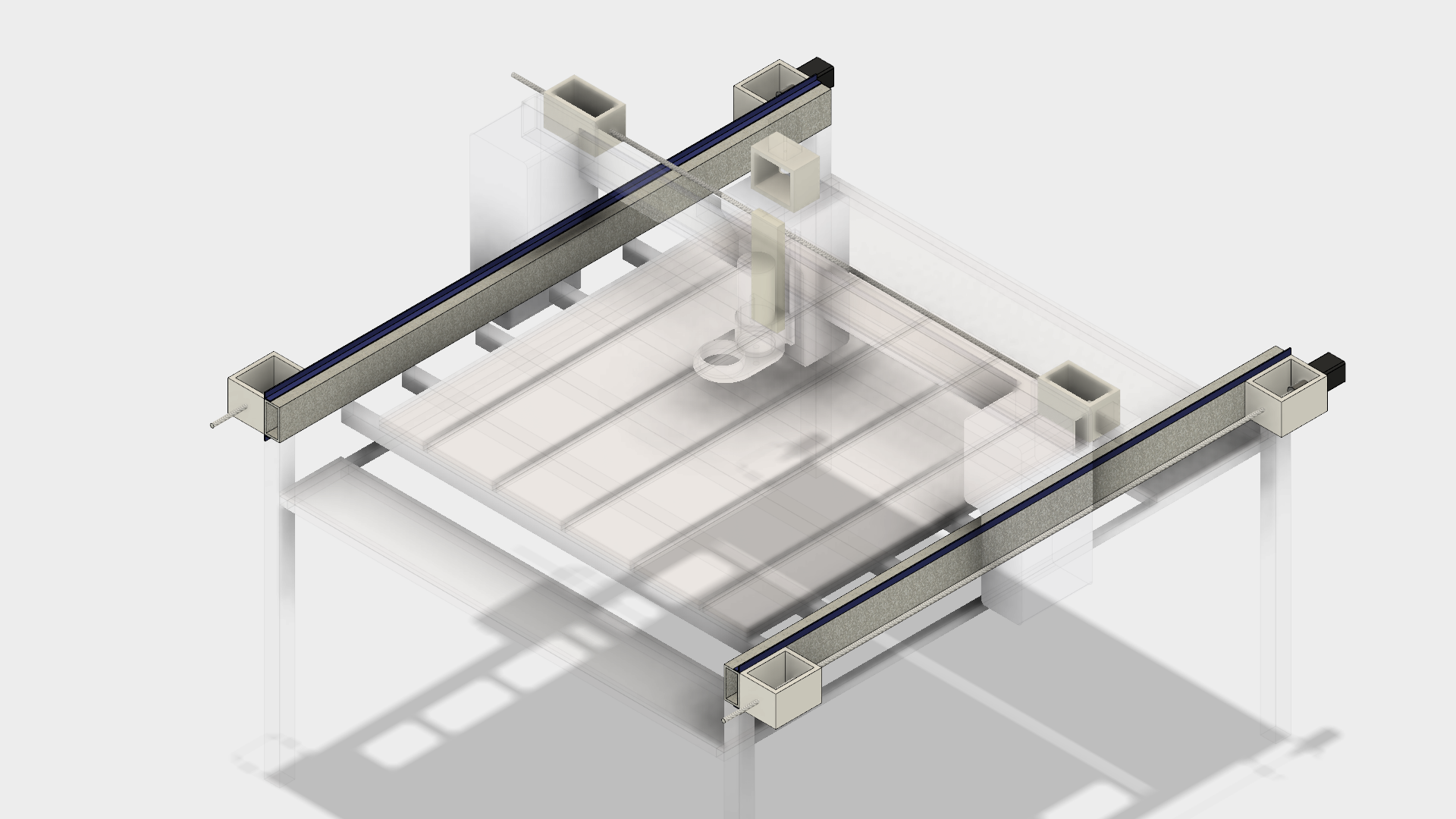 [TODO: add isolated CAD image of Y axis assembly]
- Max travel = ???
- Endstops = min and max on both sides
- Leadscrew = 1/2" x 8 TPI ACME, 8 starts
- Y axis has a tendency to bind, especially towards to maximum extremity. This seems to be due to the two gantry ends moving very slightly out of sync, but the cause (and solution) is not fully understood yet.
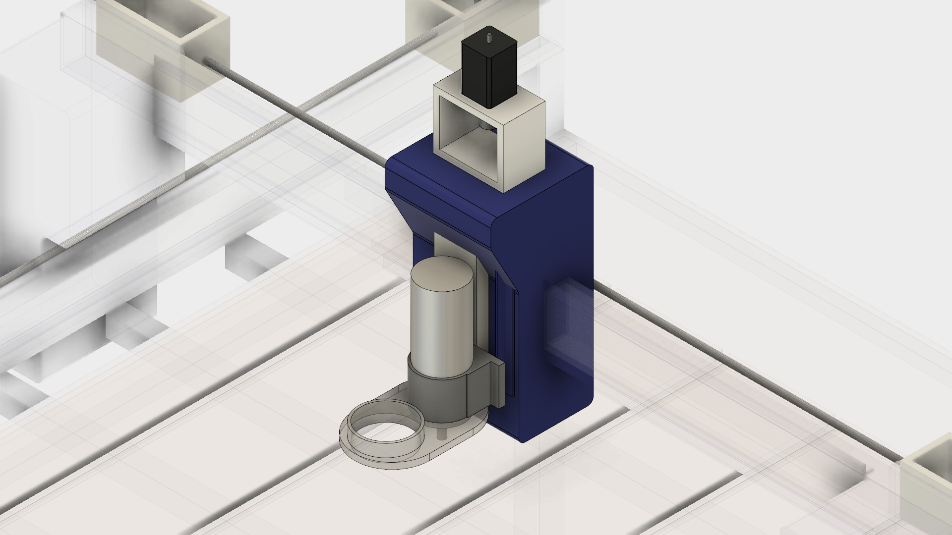 [TODO: add isolated CAD image of Z axis assembly]
- Max travel = ???
- Endstops = min only
- Leadscrew = 1/2" x 8 TPI ACME, 8 starts
- Z axis structure is mostly made of painted MDF and will likely exhibit same symptoms of wear as seen on the X axis gantry end assemblies. It does not appear to be as bad yet, but should be monitored.
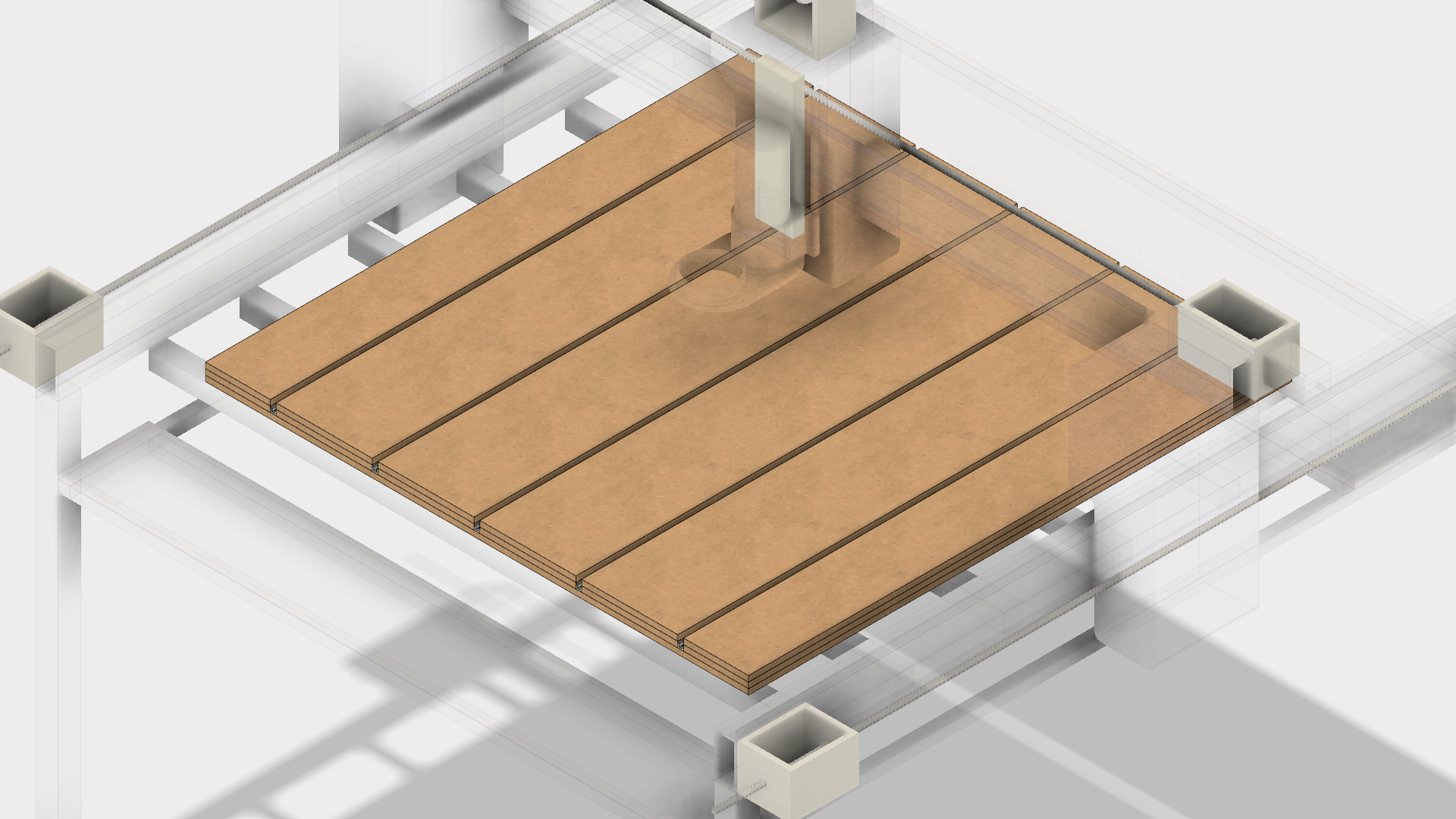 The spoilboard is currently constructed from three sheets of 1/2" MDF, with slots for bolts to use with workpiece clamps.
- Size of channels? What side bolts will fit?
- Locations of bolt holes for frame attachment. How is spoilboard built?