Electromechanical
Quick links
Stepper motors - Endstops

A total of four identical stepper motors are used to move various parts of the machine around. These NEMA 23 motors are the most powerful ones offered by HobbyCNC, and should be more than capable of providing the power needed to cut through some fairly tough materials.
Whereas the X axis and the Z axis each have dedicated stepper motors, the Y axis shares two motors for more even movement of the gantry (so long as the rails and gantry are perfectly parallel).
- Model = 23-305-DS8A
- Size = NEMA 23
-
Torque rating
- 425 oz-in bipolar (this is how we've wired them up)
- 305 oz-in unipolar
- Voltage = 4.2V
-
Current rating (per phase)
- 2.12A bipolar
- 3.0A unipolar
- Steps per revolution = 200
- Shaft diameter = 1/4"
We are wiring the stepper motors in bi-polar configuration, which involves tying the center-most phases together ultimately form two phases (thus "bi-polar").
For these motors this means tying together the yellow and blue wires, as well as tying together the orange and black wires.

| Color | Phase | DB9 pin |
|---|---|---|
| Red | A | 5 |
| Yellow | A common | 4 |
| Blue | A common | 4 |
| Black | !A | 9 |
| White | B | 2 |
| Orange | B common | 3 |
| Brown | B common | 3 |
| Green | !B | 1 |
- Visit the product page
- Download the datasheet from /docs/electronics
- Visit the "Mechanical" page to read about how the motors work with the kinematics system
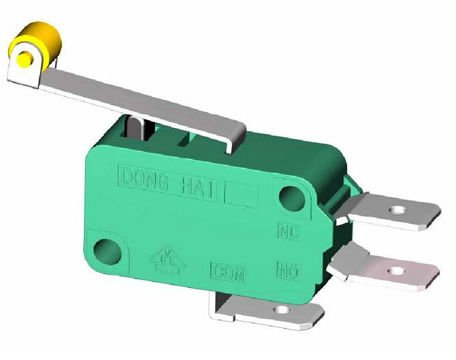
Endstops are mechanical switches that are rigidly mounted at the extreme ends of all linear motion rails such that the control hardware and software can accurately sense when it needs to stop, even if the current command is telling it to continue. This is necessary for the safe operation of the machine, especially with new users, large designs and/or high speeds.
Endstops also enable us to "home" the machine, which makes sure that the physical position of the machine in space matches the position that the host software believes it to be at.
- X axis uses two endstops - one for min and one for max.
-
Y axis uses four endstops - two per side for both min and max.
- Both of the min endstops are wired up in series such that the control board (MESA 7i76) only sees a change in signal when both of the switches are actuated, thus indicating that both ends of the gantry are moving in sync. The max endstops are wired up the same way.
- Z axis uses one endstop for the min position only.
The endstops are wired such that they always pass a positive voltage (supplied at the GND pin) back to the 7i76 breakout board until the switch is actuated. Actuating the switch breaks this circuit, which the 7i76 reads as a "low" or "0" state.
| Terminal | Audio jack pin |
|---|---|
| NC | Tip |
| NO | - |
| GND | Sleeve |
- Visit the "Mechanical" page to read about how and where the endstops are mounted